186CNV: Installation Instructions
Manufacturer reserves the right to change, at any time, specifications and designs without notice and without obligations.
10
A200035
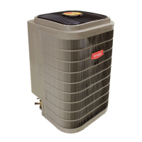
Fig. 16 – Select Line Set Length & Vapor Line Diameter
A200036
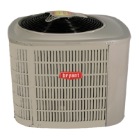
Fig. 17 – Adjust Line Set Length & Vapor Line Diameter that is
Installed
A200037
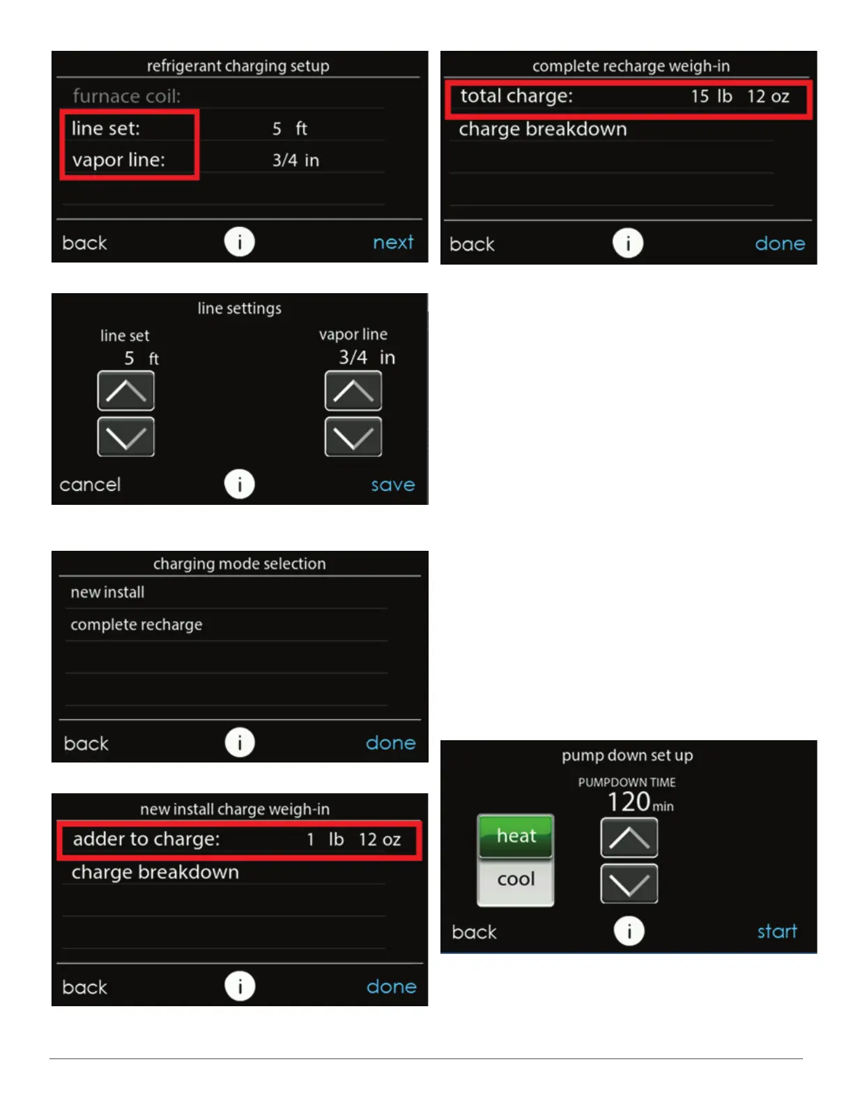
Fig. 18 – Charging Mode Selection
A200038
Fig. 19 – Additional Required Charge for New Installation
A200039
Fig. 20 – Total Charge Required for a Complete Charge
Step 12 – Pumpdown & Evacuation
Because this system has an inverter controlled compressor the
conventional procedure cannot be used to "pump down" and isolate the
refrigerant into the outdoor unit. The UI (User Interface) has provisions
to assist in performing this function. Pump Down
1. Connect gages to liquid and vapor or suction capillary service ports
to monitor operating pressures during and at completion of the
procedure.
2. In the "installation and service" menu of the UI (see Fig. 10), go to
"refrigerant charging" and then "pump down" (see Fig. 10 &
Fig. 11).
3. Pump down in COOL mode allows refrigerant to be isolated in
outdoor unit. Set desired time period. Default time period for the
procedure is 120 minutes. See Fig. 21.
4. Select Start on UI to begin the pumpdown process. Unit will begin
running in selected mode after a brief delay and a status screen will
be displayed. See Fig. 22.
5. Close the liquid service valve.
6. The unit will run with the low pressure protection set to indicate
pumpdown is complete when the suction pressure drops below 20
psig. Compressor protections are still active to prevent damage to
the compressor or inverter (high pressure, high current, etc.).
7. Once system indicates pumpdown complete or failure to complete
shutdown, close vapor service valve.
8. A recovery system will be required to remove final quantity of
refrigerant from indoor coil and line set.
9. Remove power from indoor and outdoor unit prior to servicing unit.
A200040
Fig. 21 – Pump Down Setup Screen