186CNV: Installation Instructions
Manufacturer reserves the right to change, at any time, specifications and designs without notice and without obligations.
11
A200041
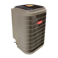
Fig. 22 – Pump Down Status Screen
Evacuation and Recovery of Refrigerant from within
186CNV
Because the 5 ton unit has an EXV for the vapor injection device,
additional steps must be taken to open the EXV if the OD unit must be
evacuated for service reasons. If the EXV is not open when pulling a
vacuum or recovering refrigerant from the OD unit, extended evacuation
time may be required and/or inadequate vacuum obtained. The UI (User
Interface) has provisions to open the EXV for refrigerant recovery
and/or evacuation.
1. Connect gages to liquid and vapor or suction capillary service ports
to monitor operating pressures during and at completion of the
procedure. Attach recovery system or vacuum pump to gage set as
needed for the service procedure. The service valves must be open
to evacuate the unit through the line set service ports. The suction
capillary service port is a direct connection to the suction port of the
compressor.
2. In the "installation and service" menu of the UI (see Fig. 10), go to
"refrigerant charging" and then "evacuation" (see Fig. 11) and
Fig. 12).
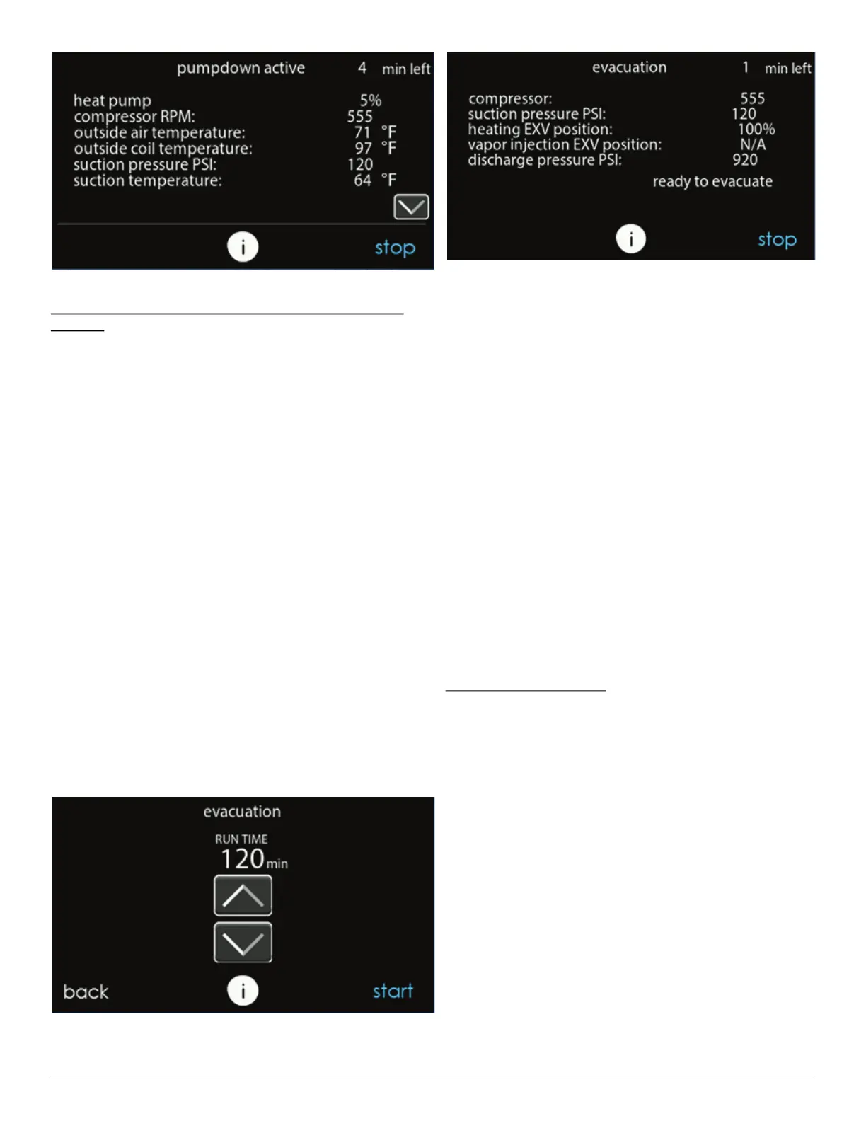
3. Set desired time period. Default time period for the procedure is
120 minutes. See Fig. 23.
4. Select START on UI to open the valve.
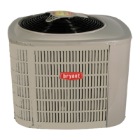
5. Begin evacuation or refrigerant recovery as required for the
procedure after UI indicates the EXV is open. Power may be
removed from outdoor unit after the UI indicates "READY TO
EVACUATE." See Fig. 24.
6. Remove power from indoor and outdoor unit prior to servicing unit.
The EXV will retain the open position.
NOTE: See service training materials for troubleshooting the EXV
using EXV CHECK mode.
A200042
Fig. 23 – Evacuation Setup Screen
A200043
Fig. 24 – Evacuation Status Screen
Step 13 – System Functions and Major Components
The 186CNV models utilize an Evolution Communicating User
Interface (UI). When a demand for cooling exists, the wall control will
direct the outdoor unit to operate at the minimum required speed to
satisfy demand. With a call for cooling, the outdoor fan is energized
followed by the compressor to run at a start speed. Once the start criteria
is met the compressor and fan will ramp to the target demand. If
continued operation at the initial speed does not satisfy demand, the
system will ramp up in 60 RPM increments until it satisfies the demand.
After coping with the higher demand, the unit returns to lower capacity
operation until the demand is satisfied or until an increase in demand
occurs. Ideal performance is achieved when system operates
continuously at the lowest speed possible, minimizing variation in
conditioned space temperatures while using minimal power.
As the unit operates at lower capacity, system vapor (suction) pressure
will be higher than it is during a standard single-stage system operation
or during a higher capacity operation.
When all demand is satisfied, the compressor will shut off. An internal
pressure equalization valve will energize during the off-cycle to allow
for easy start up at the next call for cooling.
The user interface (UI) displays the operation mode and fault codes as
specified in the troubleshooting section. See Table 7 for codes and
definitions.
NOTE: Only one code will be displayed on the outdoor unit control
board (the most recent, with the highest priority). The latest codes are
stored and can be accessed via the UI.
Primary Control Module
The Primary Control Module (PCM) controls the various functions of
the outdoor unit. The PCM has the following outputs:
1. Vapor Injection EXV
2. VFD Modbus communication
3. VFD low-voltage relay control
4. Pressure Equalization valve
5. O signal
6. W signal
7. Liquid Line Solenoid
The PCM has the following inputs:
1. Outdoor discharge thermistor (ODT)
2. Outdoor ambient thermistor (OAT)
3. Outdoor coil thermistor (OCT)
4. Discharge & suction pressure transducers (OPT)
5. Service Interface communication port
6. CCN communication (ABCD plug)
7. Model plug
8. 24VAC input power
The PCM receives a cooling demand from the wall control and
determines the appropriate compressor, fan, PEV, and LLS action based
upon the various sensor inputs.