186CNV: Installation Instructions
Manufacturer reserves the right to change, at any time, specifications and designs without notice and without obligations.
4
Step 5 – Elevate Unit
Elevate unit per local climate and code requirements to provide
clearance above estimated snowfall level and ensure adequate drainage
of unit.
Step 6 – In Long-Line Applications, Install Liquid-Line
Solenoid Valve (LSV)
For refrigerant piping arrangements with equivalent lengths of greater
than 80 ft. (24.38 m) and/or when elevation difference between indoor
and outdoor unit is greater than ±20 ft. (±6.10 m), follow the piping
configuration and liquid line solenoid valve (LSV) accessory
requirements from the Residential Piping and Long-line guideline. CCH,
start gear and piston changes do not apply. If required by Long-Line
Guideline, install LSV kit, part no. KHALS0401LLS. LSV should be
installed within 2 ft. (0.61 m) of outdoor unit with flow arrow pointing
toward outdoor unit.
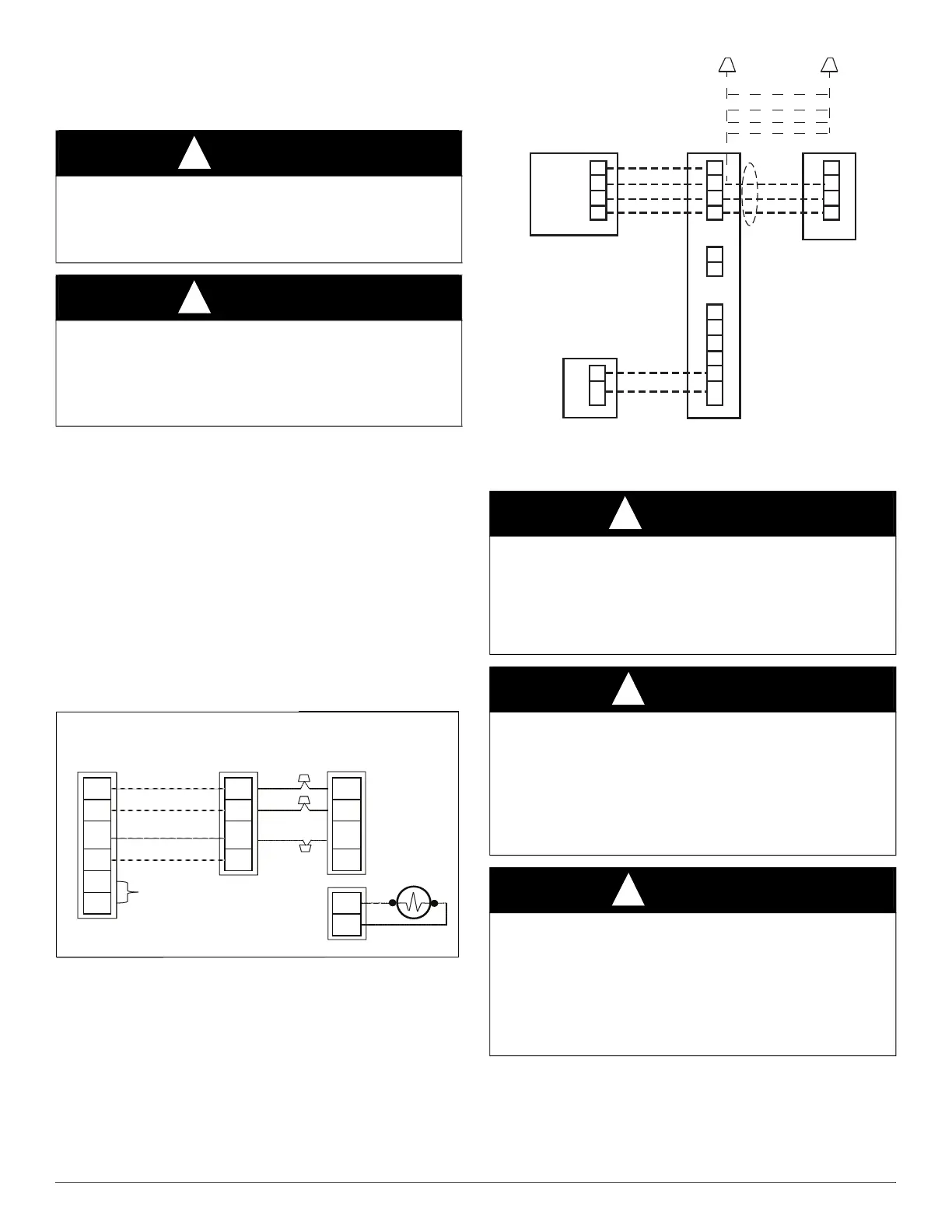
Make the necessary electrical connections as shown in Fig. 3 and Fig. 4
and by following the Installation Instructions included with accessory
kit.
IMPORTANT: Flow arrow must point toward outdoor unit.
A180243
Fig. 3 – Liquid Line Solenoid Electrical Connection
(Required for long line applications)
A200204
Fig. 4 – Evolution Furnace or Fan Coil Wiring with Communicating
Variable Speed AC
Step 7 – Make Piping Connections
Outdoor units may be connected to indoor section using accessory
tubing package or field-supplied refrigerant grade tubing of correct size
and condition. For tubing requirements beyond 80 ft. (24.38 m),
substantial capacity and performance losses can occur. Follow the pipe
sizing recommendations in the 186CNV Product data to manage these
losses.
CAUTION
!
UNIT OPERATION HAZARD
Failure to follow this caution may result in equipment damage or
improper operation.
Do not allow water and/or ice to build up in base pan.
CAUTION
!
UNIT OPERATION HAZARD
Failure to follow this caution may result in equipment damage or
improper operation.
Locate the unit in such a way that it is stable in all circumstances
including adverse weather conditions.
Furnace or
Fan Coil
Variable Speed
AC or HP
WARNING
!
PERSONAL INJURY AND UNIT DAMAGE
HAZARD
Failure to follow this warning could result in personal injury or death.
Relieve pressure and recover all refrigerant before system repair or
final unit disposal. Use all service ports and open all flow-control
devices, including solenoid valves.
CAUTION
!
UNIT DAMAGE HAZARD
Failure to follow this caution may result in equipment damage or
improper operation.
Do not leave system open to atmosphere any longer than minimum
required for installation. PVE oil in compressor is extremely
susceptible to moisture absorption. Always keep ends of tubing sealed
during installation.
CAUTION
!
UNIT DAMAGE HAZARD
Failure to follow this caution may result in equipment damage or
improper operation.
If ANY refrigerant tubing is buried, provide a 6 in. (152.4 mm) vertical
rise at service valve. Refrigerant tubing lengths up to 36 in. (914.4 mm)
may be buried without further special consideration. Do not bury lines
longer than 36 in. (914.4 mm).
D
C
B
A
Wall Control
HP or AC
OAT
RYOWCHUM
C
Humidifier
24vac
Furnace or Fan Coil
’C’ connection optional
D not required
C
B
A
D
C
B
A