Do you have a question about the Bryant Evolution SYSTXBBUID01--D and is the answer not in the manual?
Alerts users to potential personal injury with signal words DANGER, WARNING, CAUTION.
Describes the Evolution System, components, and communication.
Instructions for inspecting equipment upon arrival and filing claims for damage.
Guidelines for selecting a suitable location and wiring the control.
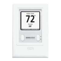
Explains the use and wiring of remote room sensors.
Steps for removing existing controls and mounting the new Evolution Control.
Information on the optional decorative backplate for aesthetics.
Shows typical wiring for various Evolution System components.
Specific wiring for furnace/fan coil with 1-stage AC.
Specific wiring for fan coil with non-communicating 1-stage HP.
Details the ABCD connector and its pin assignments.
Describes the initial power-up sequence and communication checks.
Guides the installer through selecting the outdoor unit type and size.
Instructions for identifying and configuring the electric heater size.
Allows selection of the air filter type installed in the system.
Enables configuration for humidifier installation.
Allows selection of UV light installation status.
Displays a summary of all detected and selected system equipment.
Details the static pressure check performed after setup.
Shows a summary of all detected system equipment.
Used for adding, changing, or uninstalling equipment.
Configures thermostat settings like auto mode, deadband, offsets, and elevation.
Configures furnace settings for airflow, staging, and operation.
Adjusts airflow for dehumidification mode.
Enables or disables increased furnace airflow for bypass humidifiers.
Controls furnace staging behavior based on demand and capability.
Configures G terminal operation for fan control or shutdown.
Configures fan coil airflow for heat pump heating.
Configures fan coil airflow for heat pump cooling.
Adjusts airflow for dehumidification mode.
Sets the size of the electric heater for the fan coil.
Prevents electric heat operation above a set outdoor temperature.
Configures G terminal operation for fan control or shutdown.
Configures lockout temperatures and staging times for hybrid heat.
Determines if the furnace operates during defrost cycles.
Sets time before furnace runs after heat pump demand.
Configures lockout temperatures and airflow for hydronic heat.
Determines if the water coil operates during defrost cycles with water.
Selects desired airflow during hydronic heating.
Exercises the furnace or gas packaged unit.
Exercises the electric heat stages of the fan coil.
Exercises the heat pump in heating mode.
Exercises the heat pump or AC in cooling mode.
Displays current operating parameters of furnace/PAC.
Displays current operating parameters of fan coil.
Displays current operating parameters of heat pump/AC.
Shows the last 10 system events and faults.
Explains the different fan operation modes.
Prevents compressor from starting too soon after shutdown.
Allows manual override of heat source selection.
Describes how to lock and unlock the keypad.
Explains the auto mode transition between heating and cooling.
Describes the smart recovery feature for temperature transitions.
How cooling airflow settings affect dehumidification.
Controls over-cooling for humidity removal.
Sets outdoor temperature above which furnace operates.
Sets outdoor temperature below which heat pump operates.
Manages furnace operation during defrost cycles.
Steps to resolve power issues with the Evolution Control.
Troubleshooting steps for indoor unit communication loss.
Troubleshooting steps for outdoor unit communication loss.
Guide to re-entering the start-up sequence.
Steps to view current system status and faults.
Lists system malfunction codes for fan coil units.
Lists system malfunction codes for furnaces.
Lists system malfunction codes for outdoor units.
Lists system malfunction codes for the user interface.
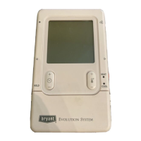
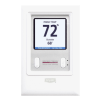
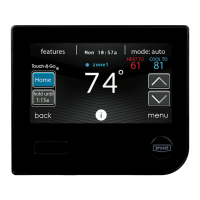
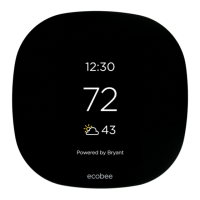
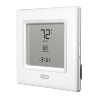
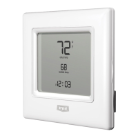
The Bryant SYSTXBBUID01-D Evolution™ Control is an intelligent communicating thermostat designed to manage a complete HVAC system, offering advanced comfort, versatility, and simplicity. It serves as the central command center for the Evolution System, replacing conventional thermostats and providing a single wall control for all system features.
The Evolution Control is the user interface for the Evolution System, which comprises several intelligent communicating components, including variable-speed furnaces or FE fan coils, 2-stage AC or heat pumps, and Evolution Packaged Products. These components continuously communicate via a four-wire ABCD bus, exchanging commands, operating conditions, and other data to optimize system performance.
The control supports various system configurations, including communicating indoor and outdoor units, or communicating indoor units with standard 24VAC controlled outdoor units. It also integrates with accessories such as humidifiers, ventilators, and UV lights. When conventional outdoor units are used, the Evolution furnace or fan coil provides the necessary 24-volt signals for control. Additionally, the Evolution Network Interface Module (NIM) allows for the connection of a Bryant HRV or ERV without requiring a separate wall control.
The system offers precise temperature and humidity control, with advanced features like variable-speed operation for furnaces and fan coils, multi-stage heating and cooling, controlled ventilation, humidification, dehumidification, and air quality management.
The Evolution Control is designed for user-friendly operation, providing homeowners with comprehensive control over their HVAC system.
The Evolution Control provides several features to assist with system maintenance and troubleshooting.
| Product Type | Thermostat |
|---|---|
| Series | Evolution |
| Compatibility | Bryant Evolution System |
| Connectivity | Wi-Fi |
| Display | Yes |
| Mobile App | Yes |
| Remote Access | Yes |
| Energy Saving Features | Yes |
| Voice Control | No |
| Programmable | Yes |
| Humidity Control | Yes |
| Dehumidification | Yes |
| Indoor Temperature Sensor | Yes |
| Outdoor Temperature Sensor | Yes |
| Type | Smart Thermostat |
| Power Source | 24VAC |
| Display Type | Touchscreen |