NOTE: Read the entire instruction manual before starting the
installation.
This symbol → indicates a change since the last issue.
TABLE OF CONTENTS
SAFETY CONSIDERATIONS.....................................................1
INTRODUCTION..........................................................................1
INSTALLATION AND START-UP OVERVIEW......................1
INSTALLATION...........................................................................1
INITIAL POWER-UP....................................................................5
QUICK START..............................................................................6
INSTALL / SERVICE MENUS....................................................7
OPERATIONAL INFORMATION.............................................11
TROUBLESHOOTING ...............................................................12
SAFETY CONSIDERATIONS
Read and follow manufacturer instructions carefully. Follow all
local electrical codes during installation. All wiring must conform
to local and national electrical codes. Improper wiring or installa-
tion may damage Evolution Control System. Recognize safety
information. This is the safety-alert symbol
. When you see this
symbol on the equipment and in the instruction manual, be alert to
the potential for personal injury. Understand the signal words
DANGER, WARNING, and CAUTION. These words are used
with the safety-alert symbol. DANGER identifies the most serious
hazards, which will result in severe personal injury or death.
WARNING signifies a hazard, which could result in personal
injury or death. CAUTION is used to identify unsafe practices,
which would result in minor personal injury or product and
property damage. NOTE is used to highlight suggestions which
will result in enhanced installation, reliability, or operation.
INTRODUCTION
The Evolution System consists of intelligent communicating
components (User Interface, variable speed furnace or fan coil, AC
or HP), which continually communicate with each other via a
four-wire connection called the ABCD bus. Conventional 24-volt
signals on dedicated wires are not needed. Commands, operating
conditions, and other data are passed continually between the
components over the ABCD bus. The result is a new level of
comfort, versatility, and simplicity.
An Evolution System consists of a Evolution Control™ (thermo-
stat plus much more) and a variable-speed furnace or FE fan coil.
They support controlled ventilation, humidification, dehumidifica-
tion, and air quality control. Either a two-speed (communicating),
or a standard 24 vac controlled outdoor unit may be used.
When using conventional outdoor units, the variable-speed furnace
or fan coil provides the 24 volt signals needed to control them.
Also, the Evolution Network Interface Module (NIM) allows
connection of a conventional HRV or ERV without the need for a
separate wall control.
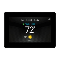
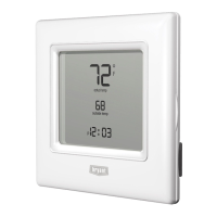
All system components are controlled through the wall mounted
Evolution Control™, which replaces the conventional thermostat
and provides the homeowner with a single wall control for all the
features of the system.
INSTALLATION AND START-UP OVERVIEW
This instruction covers installation of the Evolution Control™
only. Physical installation instructions for the indoor, outdoor
equipment and accessories are provided with each unit.
Setup, commissioning, operation, and troubleshooting of the
Evolution System is covered only in this installation instruction. It
is your guide to connecting the system components and commis-
sioning the system once all the physical components are installed.
Special screen prompts and start-up capabilities are provided in the
Evolution System to simplify and lead you through the initial
commissioning of the system. So:
• Install the Evolution Control™ according to this instruction.
• Install the indoor unit, outdoor unit, and accessories according
to their instructions.
• Wire the complete system according to this instruction.
• Setup, commission, and operate the system according to this
instruction to assure yourself a smooth and trouble free
start-up.
INSTALLATION
A. Step 1 — Check Equipment and Job Site
INSPECT EQUIPMENT — File claim with shipping company,
prior to installation, if shipment is damaged or incomplete.
HOLD
COOL
HEAT
OFF
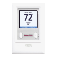
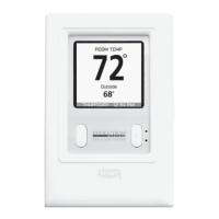
Evolution Control™
SYSTXBBUID01
A03149
Installation and Start-Up Instructions
Evolution™ Control
SYSTXBBUID01
Cancels: NEW II UID01-0-1
02-04
—1—