Do you have a question about the Bryant Evolution Connex Control SYSTXBBECC01-C and is the answer not in the manual?
Details critical safety precautions for installation, including electrical hazards and personal injury risks.
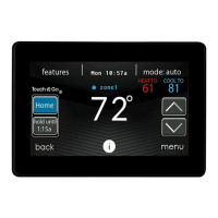
Overview of the Evolution System's intelligent communicating components and the ABCD bus.
Configure the system's time and date, allowing manual adjustment or web synchronization.
Procedure to upload dealer contact information and logo to the control.
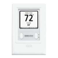
Guidance on installing the Evolution Connex Control and associated system components.
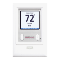
Guidelines for optimal placement of the wall control and sensors for accurate readings.
Using remote sensors to improve temperature accuracy and sensor averaging methods.
Utilizing Smart Zone Sensors for individual zone temperature control.
Guidelines for thermostat wire, shielded cable, and ABCD connector color coding.
Connecting humidifiers (bypass/fan powered) and ventilators (ERV/HRV).
Control scans and identifies indoor and outdoor units for system configuration.
Choose installed indoor coil and electric heater size for system setup.
Perform airflow checks and duct assessments for optimal system performance.
Instructions on how to enter and use the service menus for system information.
View operational status and diagnostic information for key system components.
Access fault history, cycle counts, run times, and equipment identification.
Enter lineset length and vapor line diameter for proper refrigerant charging.
Steps for isolating refrigerant (pump down) and performing system evacuation.
Load dealer logo and contact info onto SD card and upload to the control.
Establish Wi-Fi connectivity using SSID and password.
Enter the Wi-Fi network security key using the on-screen keyboard.
Diagram illustrating ABCD wiring for User Interface, Furnace/Fan Coil, and AC/HP.
Wiring configurations for zoned systems with communicating and non-communicating units.
Diagram for connecting ventilators (HRV/ERV) to the system.
Device complies with FCC Part 15, limits for Class B digital devices.
Information regarding compliance with RF exposure limits and antenna separation.
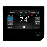
| Product Type | Thermostat |
|---|---|
| Series | Evolution |
| Model Number | SYSTXBBECC01-C |
| Wi-Fi Connectivity | Yes |
| Display | Touchscreen |
| Color | White |
| Programmability | 7-day programmable |
| Remote Access | Yes |
| Humidity Control | Yes |
| Dehumidification | Yes |
| Energy Monitoring | Yes |
| Compatibility | Bryant Evolution System |
| Energy Saving Features | Energy Reports |
| Power Method | 24VAC or Battery |
| Alerts | Yes |
| Voice Control | Compatible with Amazon Alexa and Google Assistant |
| Mobile App | Yes, Bryant Home App |