EasyManua.ls Logo

Bryant EB-STATE3LTBR-01 - User Manual

Bryant EB-STATE3LTBR-01
20 pages
Print Icon
To Next Page IconTo Next Page
Loading...
Advanced Installation and Configuration Instructions
Table of Contents
Safety Considerations . . . . . . . . . . . . . . . . . . . . . . . . . . . . . . . . . . . . . . . 1
Introduction. . . . . . . . . . . . . . . . . . . . . . . . . . . . . . . . . . . . . . . . . . . . . . . 1
How to use this document. . . . . . . . . . . . . . . . . . . . . . . . . . . . . . . . . . . . 1
Hardware Differences . . . . . . . . . . . . . . . . . . . . . . . . . . . . . . . . . . . . . . . 2
Print Label. . . . . . . . . . . . . . . . . . . . . . . . . . . . . . . . . . . . . . . . . . . . . . . . 2
Wiring Diagrams. . . . . . . . . . . . . . . . . . . . . . . . . . . . . . . . . . . . . . . . . . . 3
Start-Up –> Dehum for Fan Coil or Furnace . . . . . . . . . . . . . . . . . . . . 10
Safety Considerations
Read and follow manufacturer instructions carefully. Follow all local
electrical codes during installation. All wiring must conform to local and
national electrical codes. Improper wiring or installation may damage
Thermostat.
Recognize safety information. This is the safety-alert symbol . When
you see this symbol on the equipment and in the instruction manual, be
alert to the potential for personal injury.
Understand the signal words DANGER, WARNING, and CAUTION.
These words are used with the safety-alert symbol. DANGER identifies
the most serious hazards which will result in severe personal injury or
death. WARNING signifies a hazard which could result in personal
injury or death. CAUTION is used to identify unsafe practices which
may result in minor personal injury or product and property damage.
NOTE is used to highlight suggestions which will result in enhanced
installation, reliability, or operation.
Introduction
The ecobee Smart Thermostat Pro with voice control, Powered by
Bryant and the ecobee3 lite Pro, Powered by Bryant provides your
customers with freedom and flexibility to manage their home
environment. These thermostats help homeowners conserve energy, save
money and reduce their environmental impact. They support a furnace
with AC and up to 2-stages of heat. For heat pumps (air to air or
Geothermal) they support up to four stages of heat (2-stage heat pump,
2-stage auxiliary heat) and two stages of cool. For these systems the
thermostats can control a single accessory, such as a humidifier,
dehumidifier, ventilator, HRV or ERV. Also, the thermostats can be
installed with the PEK if a C wire isn't present. Additionally, the
thermostats can control boilers with or without an AC. When connected
to a boiler, the thermostats support up to 2-stage of heat and 2-stages of
cool and a single accessory, such as a humidifier, dehumidifier,
ventilator, HRV or ERV. When used with a boiler they cannot be
installed with the PEK if a C wire isn't present, the C wire must come
from the air handler, not the boiler.
How to use this document
The advanced installation and configuration instructions are intended to
supplement the standard installation instructions shipped with the
thermostat or available for download on www.HVACpartners.com. The
advanced settings and configuration options detailed in this document
are intended for professional installers only. Incorrect configuration may
lead to improper operation and equipment damage.
Each section of this document is outlined in the following structure:
Section Title
Location of this section within the thermostat menus.
Image showing available features in this section on the thermostat.
Feature Title
Feature Description
Default Configuration
Configuration Options
Image showing screen on the thermostat
EB-STATE3LTBB-01, EB-STATE3LTBR-01,
EB-STATE5BB-01, EB-STATE5BR-01
A200491
ecobee Smart Thermostat Pro with voice control, Powered by Bryant
A200492
ecobee3 lite Pro, Powered by Bryant
WARNING
!
ELECTRICAL OPERATION HAZARD
Failure to follow this warning could result in personal injury or death.
Before installing, modifying, or servicing system, main electrical
disconnect switch must be in the off position. There may be more than
1 disconnect switch. Lock out and tag switch with a suitable warning
label.
CAUTION
!
ELECTRICAL OPERATION HAZARD
Failure to follow this caution may result in equipment damage or
improper operation.
Improper wiring or installation may damage the thermostat. Check to
make sure wiring is connect before proceeding with installation or
turning on unit.
Question and Answer IconNeed help?

Do you have a question about the Bryant EB-STATE3LTBR-01 and is the answer not in the manual?

Summary

Safety and Document Guidance

Safety Considerations

Adherence to safety symbols and signal words for hazard identification.

Wiring Diagram Fundamentals

Conventional System Wiring

Wiring for single and multi-stage conventional HVAC systems.

Power Extender Kit (PEK) Wiring

Using the PEK for 4-wire thermostat installations.

System-Specific Wiring

Heat Pump with Auxiliary Heat

Wiring diagram for heat pumps with auxiliary heat sources.

Boiler with Fan Coil System

Wiring for boilers connected to fan coil units.

Combined and Boiler Systems

Air Conditioner with Boiler Wiring

Wiring configuration for systems with AC and a boiler.

Boiler-Only System Wiring

Wiring for boilers without a common wire connection.

Dehumidification and Initial Setup

DH;DEHUM Terminal Usage

Using accessory terminals for dehumidification on fan coils.

Start-Up Configuration Steps

Heat Pump and Dehumidifier Settings

Heat Pump Optimization

Furnace and Humidifier Settings

Dehumidification and Cooling Thresholds

Staging and Heat Pump Efficiency

Reverse vs. Standard Staging

Understanding and configuring staging logic for HVAC systems.

Heat Pump Efficiency Optimization

Maximizing heat pump efficiency and minimizing auxiliary heat use.

Auxiliary Heat Control

System Protection and Access

Sensor Configuration

Overview

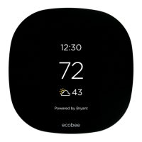
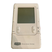
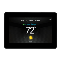
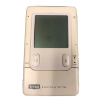
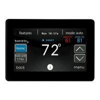
The provided document describes the Bryant ecobee Smart Thermostat Pro with voice control and the Bryant ecobee3 lite Pro, both powered by Bryant. These thermostats are designed to offer homeowners flexibility in managing their home environment, aiming to conserve energy, save money, and reduce environmental impact. The document serves as an advanced installation and configuration guide, supplementing the standard instructions. It is intended for professional installers, as incorrect configuration can lead to improper operation and equipment damage.

Function Description

These ecobee thermostats are versatile control devices for various HVAC systems. They can manage:

  • Furnaces with AC: Supporting up to 2-stages of heat.
  • Heat Pumps (air-to-air or geothermal): Supporting up to four stages of heat (2-stage heat pump, 2-stage auxiliary heat) and two stages of cool.
  • Boilers with or without AC: Supporting up to 2-stages of heat and 2-stages of cool.

The thermostats can also control a single accessory, such as a humidifier, dehumidifier, ventilator, HRV (Heat Recovery Ventilator), or ERV (Energy Recovery Ventilator). For installations where a C-wire (common wire) is not present, the thermostats can be installed with the Power Extender Kit (PEK), except when connected to a boiler, in which case the C-wire must come from the air handler.

Usage Features

The ecobee thermostats offer a range of features designed for optimal home comfort and energy efficiency:

Installation and Wiring:

  • Hardware Differences: The document illustrates the wiring terminals for both the Smart Thermostat Pro and ecobee3 lite Pro, showing connections for Rc, RH, O, G, C, Y1, Y2, W1, W2, O/B, PEK, ACC-, and ACC+.
  • Print Label: Users can identify the final assembly number, model name, country of origin, and device serial number from the print label on the back of the device.
  • Conventional System Wiring: For single-stage heat and cool, 5 wires are typically required. The thermostat needs a common wire for power. Dotted lines indicate additional wires for 2-stage equipment. The document notes that most Bryant 2-stage furnace equipment can operate with a single-stage thermostat using the furnace circuit board's algorithm for 2nd stage engagement, though a 2-stage thermostat can directly control it.
  • Power Extender Kit (PEK): The PEK allows the thermostat to operate with 4 wires instead of 5, useful for retrofit applications. It digitally combines the G and Y1 signals, which are then separated back into 24v wires at the equipment. The PEK can add one more wire to available wires, and additional wires can bypass the PEK.
  • Add-A-Wire Kit: Similar to the PEK, the Venstar Add-a-Wire Kit can be used if more than one extra wire is needed, as the PEK is limited to one. Each wire in the wall can be split using a diode to handle two terminals, with the exception of R and C.
  • Heat Pump with Auxiliary Heat Wiring: For traditional heat pumps, Y1 is the compressor and O/B is the reversing valve. O/B should be configured as an O terminal for Bryant equipment, which defaults to heating and requires the reversing valve to be energized on a cooling call. W1 is for auxiliary heat.
  • Boiler with Fan Coil Wiring: The thermostat can control two pieces of equipment with separate transformers, such as a fan coil and a boiler, requiring both Rc and Rh connections.
  • Air Conditioner with Boiler Wiring: This configuration also uses separate transformers for the AC and boiler, requiring both Rc and Rh.
  • Boiler-Only System Wiring: A common wire is still needed. If not available, a Fast-Stat Common Maker can be used to piggy-back the W call on the common wire.
  • Humidifier (1-wire) Wiring: For non-internally powered accessories, one wire connects to ACC+ on the thermostat, and the other to Common, typically at the furnace.

Initial Start-Up and Configuration:

  • Initial Configuration: Upon first power-up or reset, the thermostat guides the user through an initial configuration process.
  • Power Source Detection: The thermostat detects connected wires. For standard furnaces with AC or fan coils with heat pumps, only Rc is typically connected (single transformer). If heating and cooling equipment have separate transformers (e.g., boiler with fan coil/AC), both Rc and Rh are connected.
  • Wiring Standard: The thermostat automatically detects connected wires. If incorrect, users can check terminations or manually modify the wiring on the screen.
  • Accessory Selection: If accessories are wired to the ACC terminals, the type (Humidifier, Dehumidifier, Ventilator) must be selected.
  • Dehumidifier for Fancoil or Furnace: When selecting a dehumidifier using the equipment's DHUM or DH terminal, the appropriate relay action (Open/Closed) must be chosen. For fan coils or furnaces, dehumidification occurs when the Dehum input is Open.
  • Heat Pump Configuration: For Bryant heat pumps, the reversing valve (O terminal) should be energized on a cooling call ("On cool"). Other manufacturers might require "On heat."
  • Auxiliary Heat Configuration: Users can enable simultaneous operation of heat pump and electric auxiliary heat (for electric resistance systems) or disable it for dual-fuel systems (fossil fuel furnace). Running compressor and furnace simultaneously is not recommended for dual-fuel systems.
  • Compressor Minimum Outdoor Temperature: This setting determines the lowest outdoor temperature at which the compressor will run. It can be set to "Auto" or disabled at a specific temperature. The document advises disabling it based on manufacturer specifications or when the heat pump's COP drops below 1.0.
  • Furnace Fan Control: For current CBP and ICP furnaces, the fan should be controlled by the furnace to delay fan engagement on W1, allowing the heat exchanger to warm up and prevent cold air blasts.
  • Humidifier Type: Typically, "Steam" should be selected, even for evaporative humidifiers, as it provides the option to humidify with the fan.

Advanced Settings (Installation Settings):

  • Dehumidification with Fan: When wired and set up with AC Overcool Max, this feature allows multiple cooling modes (temperature only, dehumidification, or both). Energizing the DH or DHUM terminal slows the variable speed blower to increase latent capacity.
  • Cool Dissipation Time: By default, this is "Auto," but setting it to "0" is recommended for most climates to allow moisture on the evaporator coil to drain, preventing re-evaporation into the home.
  • Reverse Staging: This feature allows for more efficient operation by de-energizing the second stage of heating/cooling when the room temperature approaches the setpoint, allowing the first stage to finish the cycle. This helps achieve longer total run cycles.
  • Heat Pump Optimization: Various settings aim to minimize the use of auxiliary electric resistance heat, as heat pumps are significantly more efficient.
  • Auxiliary Savings Optimization: This algorithm determines how many degrees out of the setpoint auxiliary heat will engage, ranging from a half-degree ("Minimum") to 2.5 degrees ("Maximum").
  • Auxiliary Heat Maximum Outdoor Temperature: This setting specifies the temperature above which the heat pump can handle the heating load without auxiliary electric heat. Aux heat will be locked out above this temperature. The "Thermal Break Point" can be determined using an online calculator or manually plotted.
  • Staging Configuration: If "Manual" staging is selected, additional options for auxiliary heat need to be configured. For heat pump applications, "Automatic" staging is generally recommended due to complexity.
  • Thermal Protect: This feature sets a maximum allowed temperature difference between the thermostat and other sensors. If a sensor reading is significantly outside this range, it's ignored to prevent excessive heating or cooling. This range is adjustable from 10 to 25 degrees.
  • Installer Code: Enabling this code locks out professional settings (Equipment, Thresholds, Test Equipment) to prevent homeowners from accidentally changing them. This code is fixed and not changeable.
  • Sensor Settings: Adjustments can be made for the main thermostat's sensor and remote sensors. The "Follow Me" feature allows sensors with detected occupancy to become active, averaging their readings. The thermostat gradually adjusts to prevent sudden changes. Each sensor can be assigned to Comfort Settings (Home, Away, Sleep), and their names can be adjusted.

Maintenance Features

The document does not explicitly detail maintenance features for the device itself. However, it emphasizes the importance of proper installation and configuration to ensure reliable operation and prevent damage. The "Installer Code" feature can be seen as a preventative measure to maintain system integrity by preventing unauthorized changes to critical settings.

The document also provides resources for support, including phone numbers for Pro Support and links to online resources like the Contractor Sales Tool, Contractor Portal, ecobee Mobile App, and SUPPORT.ECOBEE.COM. For training, the My Learning Center is available for professional residential HVAC training.

Bryant EB-STATE3LTBR-01 Specifications

General IconGeneral
BrandBryant
ModelEB-STATE3LTBR-01
CategoryThermostat
LanguageEnglish

Related product manuals