Do you have a question about the Bryant Evolution Connex Control and is the answer not in the manual?
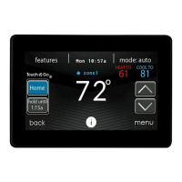
Configure system time and date manually or via web server.
Allows direct adjustment of hour, minute, month, day, and year.
Select the appropriate time zone for the system's location.
Enable automatic time synchronization for Wi-Fi enabled controls.
Upload dealer logo and contact info using PC/MAC app and SD card.
Covers installation of control, access point, and initial equipment inspection.
Guidelines for optimal placement of wall control and remote sensors.
Details on using remote sensors and their averaging capabilities.
Smart sensor usage for zoning and general wiring guidelines.
Proper wiring for communication bus and use of shielded cable.
Wiring and mounting of the Damper Control Module for zoning systems.
Installation of decorative trim plate and backplate assembly.
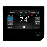
Steps for mounting the Evolution Connex Control to the wall.
Instructions for connecting bypass and fan-powered humidifiers.
Initial power-up and control communication to identify system components.
Control searches for and identifies the connected outdoor unit.
Select indoor evaporator coil and electric heater size.
Supports two types of hydronic heat applications with specific kit requirements.
Search for SAM module and identify system zones for configuration.
Select filter type, humidifier, and UV lights installed.
Review equipment summary and perform airflow verification test.
Measures ductwork size and calculates airflow for zoned systems.
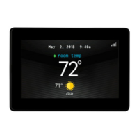
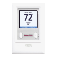
Displays indoor/outdoor unit types, filter type, accessories, and number of zones.
Access installation process and system setup configurations.
Configure thermostat parameters like Auto Mode, Deadband, and Offsets.
Adjust fan coil settings including airflow, altitude, and dehumidification.
Configure furnace airflow, staging, altitude, and G-terminal functions.
Set AC/HP parameters like lockout, defrost, low ambient, and quiet shift.
Configure Geothermal HP limits, lockout, energy tracking, and zoning.
Configure settings for filters, humidifiers, UV lights, and ventilators.
Set utility curtailment response and hydronic airflow settings.
Test and verify operation of Electric Heat, Furnace, Hydronic, AC, HP, Humidifier, Ventilator.
Perform airflow limits, damper/sensor, and zone duct assessment.
View advanced diagnostics, equipment status, event logs, and model numbers.
Guide for proper system charging, pump down, and evacuation.
Upload custom dealer logo and contact information to the control.
Enable utility event participation for the homeowner.
Establishes Wi-Fi connectivity using the in-home router SSID and password.
Establishes Wi-Fi connectivity using a dealer-provided Wireless Access Point.
Diagram showing basic four-wire connection for user interface and components.
Wiring for furnace/fan coil with 1-stage AC and 1-stage HP.
Wiring for zoning systems with various indoor/outdoor units.
Chart indicating when a Network Interface Module (NIM) is required.
Wiring diagram for single-stage non-communicating heat pump with NIM.
Wiring diagram for two-stage non-communicating heat pump with NIM.
Wiring diagram showing G input for blower operation.
Wiring diagram showing G input for system shutdown.
Details FCC compliance, limits, and measures to correct interference.
| Compatibility | Bryant Evolution System |
|---|---|
| Connectivity | Wi-Fi |
| Display | Color Touchscreen |
| Energy Saving | Yes |
| Humidification Control | Yes |
| Dehumidification Control | Yes |
| Ventilation Control | Yes |
| Remote Access | Yes |
| Geofencing | Yes |
| Humidity Control | Yes |
| Energy Monitoring | Yes |
| Alerts | Yes |
| Control | Touchscreen |
| Programming | 7-Day Programmable |
| Voice Control | Amazon Alexa |