Do you have a question about the Bryant EVOLUTION Zone Control SYSTXBBUIZ01-B and is the answer not in the manual?
Read and follow manufacturer instructions and local electrical codes for safe installation.
Guidelines for selecting the optimal location and wiring the Evolution Zone Control.
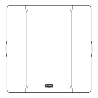
Step-by-step instructions for installing the Evolution Zone Control unit.
Details on connecting the ABCD connector for communication.
Wiring diagrams for connecting the control to various system components.
Describes the sequence of events during the initial power-up and system identification.
Guide for selecting the type and size of the outdoor unit.
Process for identifying zones and summarizing installed equipment.
Covers static pressure check and duct assessment for optimal airflow.
Guides through quick start and setting day, time, and humidity.
Procedure to enter the Install/Service menus by holding the ADVANCED button.
Steps to troubleshoot the Evolution Zone Control not powering up.
Troubleshooting common display messages like "Indoor Unit Not Found".
Explains how to interpret fault codes for Fan Coil, Furnace, and Outdoor Unit.
Identifies common faults related to the User Interface and its sensors.
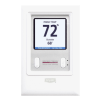
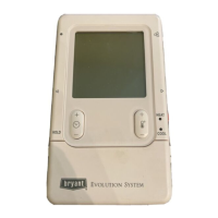
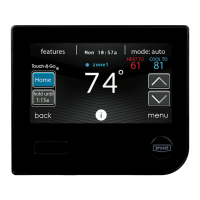
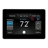
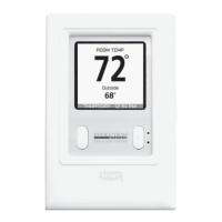
This document describes the Bryant Evolution™ Control, a sophisticated user interface that serves as the command center for the Evolution Zone System. This system integrates various intelligent communicating components, including the Evolution Zone Control (User Interface), Smart Sensors, a Damper Control Module, variable-speed furnaces or FE fan coils, 2-stage AC or HP units, and Evolution Packaged Products. These components continuously communicate via a four-wire ABCD bus, exchanging commands, operating conditions, and other data to provide enhanced comfort, versatility, and simplicity.
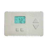
The Evolution Zone Control replaces conventional thermostats, offering a single wall control for all system features. It manages controlled ventilation, humidification, dehumidification, and air quality. The system supports both Evolution 2-stage (communicating) and standard 24VAC controlled outdoor units. When conventional outdoor units are used, the Evolution furnace or fan coil provides the necessary 24-volt signals. The Damper Control Module (P/N SYSTXBB4ZC01) allows connection of a Bryant HRV or ERV without a separate wall control.
The Evolution Zone system is designed to operate without a bypass damper, leveraging its intelligence and variable-speed motor technology. For optimal performance, zones should be sized to deliver at least the minimum airflow for the system in both heating and cooling modes, and ductwork should be oversized by 25% to minimize noise at minimum zone airflow.
The Evolution Zone Control acts as the primary temperature sensor for Zone 1 and should be located in a frequently used, easily accessible, and visible area, preferably on an inside partitioning wall without pipes or ductwork. It should be mounted approximately 5 feet (1.5 meters) from the floor and away from direct light, heat sources, supply registers, or areas with poor air circulation to ensure accurate temperature measurement.
A Remote Room Sensor can be used in place of the User Interface's internal temperature sensor, allowing the Evolution Zone Control to be mounted in less-than-optimal airflow areas. The remote sensor connects to the User Interface backplate (S1 and S2) or the Damper Control Module (OS1 and OS1C) and is automatically detected by the Evolution Zone Control. It's important to note that the humidity sensor cannot be remotely located. Smart Sensors can also be used in any zone, providing a temperature display and buttons to adjust the desired temperature, as well as displaying outdoor temperature and indoor humidity sensed at the User Interface.
The Evolution Zone Control offers a comprehensive set of features for managing home comfort:
The Evolution Zone Control includes several features to assist with system maintenance:
| Series | Evolution |
|---|---|
| Compatibility | Bryant Evolution System |
| Connectivity | Wi-Fi |
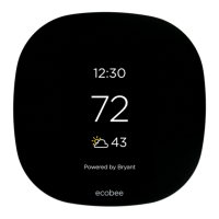
| Control | Touchscreen |
| Zoning Capability | Yes |
| Mobile App | Yes |
| Color | White |
| Programmability | 7-day programmable |
| Remote Access | Yes |
| Humidity Control | Yes |
| Dehumidification | Yes |
| Air Purification Control | Yes |
| Energy Monitoring | Yes |
| Display | Color Touchscreen |
| Voice Control | Amazon Alexa |