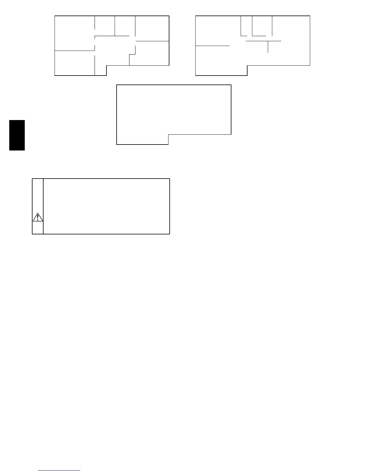
13
BASEMENT
MASTER
BEDROOM
WASH-
ROOM
#1
WASH-
ROOM
#2
BEDROOM
#3
BEDROOM
#5
BEDROOM
#4
1320 sq ft
(125 sq m) 1320 sq ft
(125 sq m)
LIVING ROOM
#6
FAMILY ROOM
#10
KITCHEN
#9
LAUNDARY
ROOM
#8
WASH-
ROOM
#7
DINING ROOM
#11
1320 sq ft
(125 sq m)
A98388
Fig. 25 --- Floor Plan Example
VENTILATION EV ALUATION
CAUTION: UNIT DAMAGE HAZARD
Failure to follow this caution may result in reduced
unit efficiency, capacity or unit life.
DO NOT use HRV during construction of a house
or when sanding drywall. This type of dust may
damage system.
When ventilation requirement is determined, use Product
Data Sheets to reference unit airflow delivery and
performance.
The ventilation capacity of an HRV unit while at maximum
speed is defined according to greatest total airflow
required. These methods are derived from the Canadian
National Building Code 1995 version and the CSA F326.1
revision.
The following 2 methods can be used to evaluate the
approximate ventilation needs of a house. Accuracy of
calculations are dependent upon the information available
and knowing critical measurements of the structure (See
Fig. 25).
METHOD 1
To calculate approximate ventilati on:
The sum of rooms X 10 CFM per room, plus 20 CFM for
a master bedroom or basement.
Example: 11 rooms X 10 CFM + 2 X 20 CFM = 150 CFM.
Note: The master bedroom and basement are not included
in first part of this equation, but figured in at second part of
equation.
METHOD 2
To calculate approximate ventilati on:
Referencing same example (See Fig. 25).
Total cu ft X 0.3 per hr = total. Take total and divide by
60 to get CFM.
Example:
1320 sq ft X 8 ft in height = 10560 cu ft per floor
10560 cu ft x 3 floors = 31680 total cu ft in house
31680 cu ft X 0.3 air change per hr = 9500 cu ft
9500 cu ft ÷ 60 minimum per hr = 160 CFM.
Conclusion: The total amount of air flow needed is 160
CFM. This falls within airflow range of a HRVBBLHA1150
size unit.
CONTROL BOARD OPERATION
Step 1.—Board Function
Note: To ensure proper operation of HRV, configuration
jumpers are located on electronic control board and must
match configuration setup shown on Fig. 26 and 27. under
Jumper Table.
Jumpers are factor y set and do not require any changes
unless control board is replaced. If control board is
replaced, or you encounter unusual start---up operation,
check jumpers to make sure they are located properly (See
Fig. 26 and 27).
Step 2.—Defrost
The HRV continually monitors the outside air temperature.
Iftheoutsideairisatorbelow23°F ( --- 5 °C), the HRV will
initiate a defrost cycle by closing the outside air damper
and recirculating warm indoor air through the heat recovery
core. This happens every 32 min. with 6 m inute defrost
cycle. During this process, core is defrosted without the use
of electric strip heat. At 5°F ( --- 1 5 °C), unit will defrost for 6
minutes every 32 min. At ---17°F ( --- 2 7 °C), the unit will sense
a need to defrost every 20 minutes with a 6 minute cycle.
See the Troubleshooting section for a control logic
explanation.
Step 3.—Off and Intermittent/Off Mode
When HRV is Off, K1 relay is open, and K5 relay is
energized which closes outside air damper (See Logic
Diagram in Fig. 26 and 27).
Step 4.—High ---Speed Air Exchange
When high---speed air exchange occurs, K1 and K2 relays
are energized and K5 relay is de---energized. This opens
low---speed contacts, and closes high---speed contact on
K2 relay . This also opens contact on K5 relay which opens
outside air damper. Then, 115vac is applied between
orange and gray wires on Molex plug (pins 1 and 6) and
blower motor runs in high---speed operation. (See Logic
Diagram in Fig. 26 and 27).
HRV