8
ELECTRICAL CONNECTIONS
1. 115 ---vac Wiring
The HRV operates on 115vac. It comes with a power cord
attached to unit and ready to plug into a fused outlet. Unit
must be grounded for proper operation.
All electrical connections must comply with National and
Local Electrical Codes, or other ordinances that might
apply.
WARNING: ELECTRICAL SHOCK/FIRE HAZARD
Fail ure to follow this warning coul d result in property
or unit damage.
Do not use an extension cord as a power source for
operating the HRV.
2. 12 ---vdc W iring
The HRV circuit board, wall control, and accessories
operate on 12vdc. See Wall Control section, item Wiring
and Fig. 11 and 12 for more information.
ACCES SORIES
Note: Interlock relay is now integrated into the control.
The purpose of interlock relay is to energize indoor system
equipment (furnace or fan coil) blower whenever HRV is
calling. If HRV is energized, and indoor system equipment
is not, interlo ck relay will energize and make R and G at
indoor equipment. This will ensure fresh air distribution
throughout the building via the central duct system.
1. 20 Minute Timer
Apushbuttontimercanbeusedtooverridethewall
control and put the HRV into high speed for 20 minutes.
Connect switches in parallel and connect leads to HRV
terminals I, OC, and OL (See Fig. 13). Push button
locations are ideal in special activity areas, such as,
bathroom, or kitchen, where high---speed exhaust
operation is needed for a short period of time.
Note: The 20 minute timer will not function properly unless
HRV wall control is applied and working correctly. Timing
function is internal to electronic circuit board, it is activated by
a momentary contac t between OC and OL. The I connection
is to illuminate the push button. The maximum number of
push button timers that can be applied is 5.
2. 60 Minute Adjustable Timer
A60minuteadjustabletimercanalsobeusedtooverride
wall control and put HRV into high---speed operation for a
select amount of time. Connect timer in parallel with push
button timers, or to HRV terminals OC and OL (See Fig.
13).
The 60 minute timer will provide a minimum of 10 minutes,
and a maximum of 60 minutes of ventilation at high speed.
% D’HUMIDITE RELATIVE HUMIDITY
’
% HUM. RELATIVE HUM.
55%
45%
35%
30%
EXT. TEMP. EXT.
MODE
MAINTE NANCE
AIR EXCHANGE
ECHANGE D’AIR
’
20
25
30
40
50
60
70
80
10
o
C/50
o
F
0
o
C/32
o
F
–10
o
C/14
o
F
–20
o
C/– 4
o
F
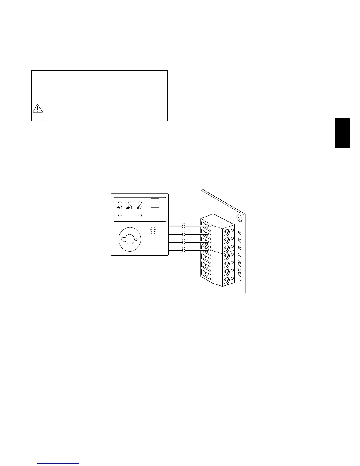
CONTROL
CONNECTOR
WALL CONTROL
YELLOW
RED
GREEN
BLACK
A98410
Fig. 12 --- Control Connections
HRV