12
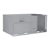
Fig. 14 — Economizer Filter Installation
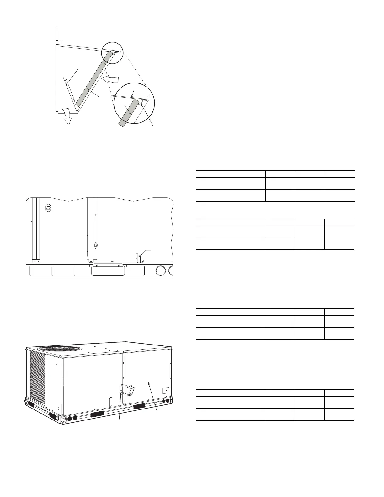
Step 9 — Units with Hinged Panels Only
Relocate latch shipped inside the compressor compartment behind
the hinged compressor door to location shown in Fig. 15 after unit
installation.
If the unit does not have hinged panels, skip this step and continue
at Step 10.
Fig. 15 — Compressor Door Latch Location
Step 10 — Install Flue Hood
Flue hood is shipped screwed to the basepan beside the burner
compartment access panel. Remove from shipping location and
using screws provided, install flue hood and screen in location
shown in Fig. 16.
Fig. 16 — Flue Hood Details
Step 11 — Install Gas Piping
Installation of the gas piping must be accordance with local build-
ing codes and with applicable national codes. In U.S.A., refer to
NFPA 54/ANSI Z223.1 National Fuel Gas Code (NFGC). In
Canada, installation must be accordance with the CAN/CSA
B149.1 and CAN/CSA B149.2 installation codes for gas burning
appliances.
This unit is factory equipped for use with Natural Gas fuel at ele-
vations up to 2000 ft (610 m) above sea level. Unit may be field
converted for operation at elevations above 2000 ft (610 m) and/or
for use with liquefied petroleum fuel. See accessory kit installation
instructions regarding these accessories.
NOTE: Furnace gas input rate on rating plate is for installation up
to 2000 ft (610 m) above sea level. The input rating for altitudes
above 2000 ft (610 m) must be derated by 4% for each 1000 ft
(305 m) above sea level.
For natural gas applications, gas pressure at unit gas connection
must not be less than 4 in. wg (996 Pa) or greater than 13 in. wg
(3240 Pa) while the unit is operating. On 582JF*05-06 (high-heat)
units, the gas pressure at unit gas connection must not be less than
5 in. wg (1245 Pa) or greater than 13 in. wg (3240 Pa) while the
unit is operating, see Table 3. For liquified petroleum applications,
the gas pressure must not be less than 11 in. wg (2740 Pa) or great-
er than 13.0 in. wg (3240 Pa) at the unit connection, see Table 4.
The gas supply pipe enters the unit at the burner access panel on
the front side of the unit, through the long slot at the bottom of the
access panel. The gas connection to the unit is made to the
1
/
2
-in.
FPT gas inlet port on the unit gas valve.
Manifold pressure is factory-adjusted for natural gas fuel use. Ad-
just as required to obtain best flame characteristics. See Table 5.
Manifold pressure for LP fuel use must be adjusted to specified
range. Follow instructions in the accessory kit to make initial read-
justment, see Table 6.
DIVIDER
BAROMETRIC
RELIEF
CLEANABLE
ALUMINUM
FILTER
FILTER
HOOD
FILTER
CLIP
OUTSIDE
AIR
COMPRESSOR DOOR
OUTDOOR COIL
LATCH
BLOWER
ACCESS
PANEL
FLUE OPENING
Table 3 — Natural Gas Supply Line Pressure Ranges
UNIT MODEL UNIT SIZE MIN. MAX.
582JD/E/L/M/S/R 04, 05, 06
4.0 in. wg
(996 Pa)
13.0 in. wg
(3240 Pa)
582JF/N/T
(High Heat Units Only)
05, 06
5.0 in. wg
(1245 Pa)
13.0 in. wg
(3240 Pa)
Table 4 — Liquid Propane Supply Line Pressure Ranges
UNIT MODEL UNIT SIZE MIN. MAX.
582JD/E/S/R 04, 05, 06
11.0 in. wg
(2740 Pa)
13.0 in. wg
(3240 Pa)
582JF/T
(High Heat Units Only)
05, 06
11.0 in. wg
(2740 Pa)
13.0 in. wg
(3240 Pa)
Table 5 — Natural Gas Manifold Pressure Ranges
UNIT MODEL UNIT SIZE HIGH FIRE LOW FIRE
582JD/E/L/M/S/R 04, 05, 06
3.5 in. wg
(872 Pa)
SEE NOTE
BELOW
582JF/N/T
(High Heat Units Only)
05, 06
3.5 in. wg
(872 Pa)
SEE NOTE
BELOW
NOTE: LOW FIRE, 1.7 in. wg (423 Pa), applies to the following three
phase voltage units only: 582JE04 and 582JF05/06.
Table 6 — Liquid Propane Manifold Pressure Ranges
unit model UNIT SIZE high fire low fire
582JD/E/S/R 04, 05, 06
10 in. wg
(2490 Pa)
SEE NOTE
BELOW
582JF/T
(High Heat Units Only)
05, 06
10 in. wg
(2490 Pa)
SEE NOTE
BELOW
NOTE: LOW FIRE, 5.0 in. wg (1245 Pa), applies to the following three
phase voltage units only: 582JE04 and 582JF05/06.

 Loading...