6
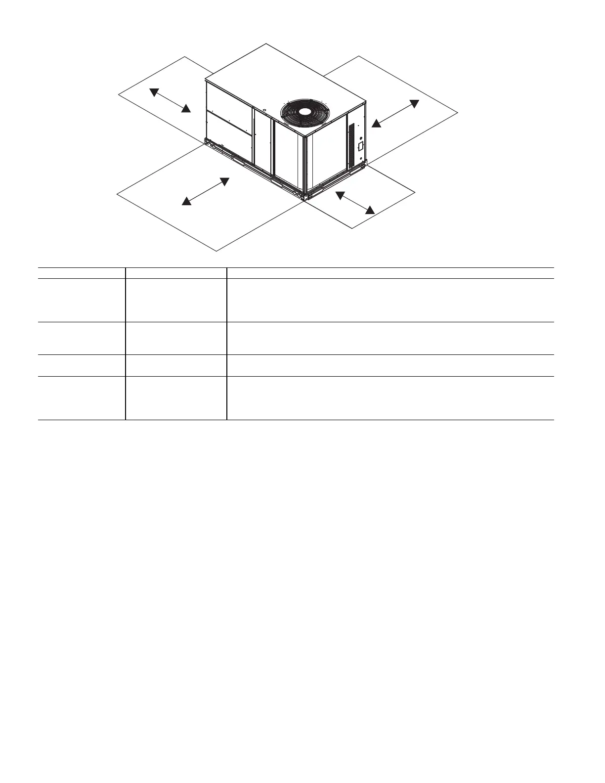
Fig. 3 — Service Clearance Dimensional Drawing
INSTALLATION
Installation of this furnace at altitudes above 2000 ft (610 m) shall
be made in accordance with the Listed High Altitude Conversion
Kit available with this furnace.
L'installation de ce générateur de chaleur à des altitudes
supérieures à 2000 pi (610 m) doit être effectuée conformément
aux instructions accompagnant la trousse de conversion pour
haute altitude fournie avec cet appareil.
Jobsite Survey
Complete the following checks before installation.
1. Consult local building codes and the NEC (National Elec-
trical Code) ANSI/NFPA 70 for special installation
requirements.
2. Determine unit location (from project plans) or select unit
location.
3. Check for possible overhead obstructions which may
interfere with unit lifting or rigging.
Step 1 — Plan for Unit Location
Select a location for the unit and its support system (curb or other)
that provides for the minimum clearances required for safety. This
includes the clearance to combustible surfaces, unit performance
and service access below, around and above unit as specified in
unit drawings. See Fig. 3.
NOTE: Consider also the effect of adjacent units.
Be sure that unit is installed such that snow will not block the
combustion intake or flue outlet.
Unit may be installed directly on wood flooring or on Class A, B,
or C roof-covering material when roof curb is used.
Do not install unit in an indoor location. Do not locate air inlets
near exhaust vents or other sources of contaminated air. For proper
unit operation, adequate combustion and ventilation air must be
provided in accordance with Section 5.3 (Air for Combustion and
Ventilation) of the National Fuel Gas Code, ANSI Z223.1 (Ameri-
can National Standards Institute) and NFPA (National Fire Protec-
tion Association) 54 TIA–54–84–1. In Canada, installation must
be in accordance with the CAN1–B149 installation codes for gas
burning appliances.
Although unit is weatherproof, avoid locations that permit water
from higher level runoff and overhangs to fall onto the unit.
Locate mechanical draft system flue assembly at least 4 ft (1.2 m)
from any opening through which combustion products could enter
the building, and at least 4 ft (1.2 m) from any adjacent building
(or per local code). Locate the flue assembly at least 10 ft (3.05 m)
from an adjacent unit’s fresh air intake hood if within 3 ft (0.91 m)
of same elevation (or per local code). When unit is located adja-
cent to public walkways, flue assembly must be at least 7 ft
(2.1 m) above grade.
Select a unit mounting system that provides adequate height to al-
low installation of condensate trap per requirements. Refer to In-
stall External Condensate Trap and Line on page 15 for required
trap dimensions.
LOCATION DIMENSION CONDITION
A
48 in. (1219 mm) Unit disconnect is mounted on panel
18 in. (457 mm) No disconnect, convenience outlet option
18 in. (457 mm) Recommended service clearance
12 in. (305 mm) Minimum clearance
B
40 in. (1067 mm) Surface behind servicer is grounded (e.g., metal, masonry wall)
36 in. (914 mm) Surface behind servicer is electrically non-conductive (e.g., wood, fiberglass)
Special Check sources of flue products within 10 ft (3 m) of unit fresh air intake hood
C
36 in. (914 mm) Side condensate drain is used
18 in. (457 mm) Minimum clearance
D
48 in. (1219 mm) No flue discharge accessory installed, surface is combustible material
42 in. (1067 mm) Surface behind servicer is grounded (e.g., metal, masonry wall)
36 in. (914 mm) Surface behind servicer is electrically non-conductive (e.g., wood, fiberglass)
Special Check for adjacent units or building fresh air intakes within 10 ft (3 m) of this unit’s flue outlet
 Loading...