6
Table 2—Accessory Usage
Accessory
REQUIRED FOR LOW---AMBIENT
APPLICATIONS
(0°FTo55°F)
REQUIRED FOR LONG LINE
APPLICATIONS* (Over 80 ft.)
Crankcase Heater Yes Yes
Evaporator Freeze Thermostat
Yes
(F or non--- Evolution systems only)
No
Winter Start Control
Yes
(F or non--- Evolution systems only)
No
Thermal Expansion Valve (TXV)
Hard Shutoff
Yes
Yes
Compressor Start Assist Capacitor a nd Relay Yes
Yes
Low---ambient Pressure Switch
Yes
(For non---Evolution system only)
No
Support Feet Recommended
No
Liquid Line Solenoid Valve No See Long---Line Application Guideline
* For Tubing Set lengths between 80 and 200 ft. horizontal or 20 ft. vertical differential (250 ft. Total Equivalent Length), refer to the Longline
Guideline --- Air Conditioners and Heat Pumps using Puron refrigerant.
INSTALL LIQUID--LINE FILTER DRIER INDOOR
CAUTION
!
UNIT DAMAGE HAZARD
Failure to follow this caution may result in equipment damage
or improper operation.
Installation of filter drier in liquid line is required.
CAUTION
!
UNIT DAMAGE HAZARD
Failure to follow this caution may result in equipment
damage or improper operation.
Filter drier must be wrapped in a heat---sinking material
such as a wet cloth while brazing.
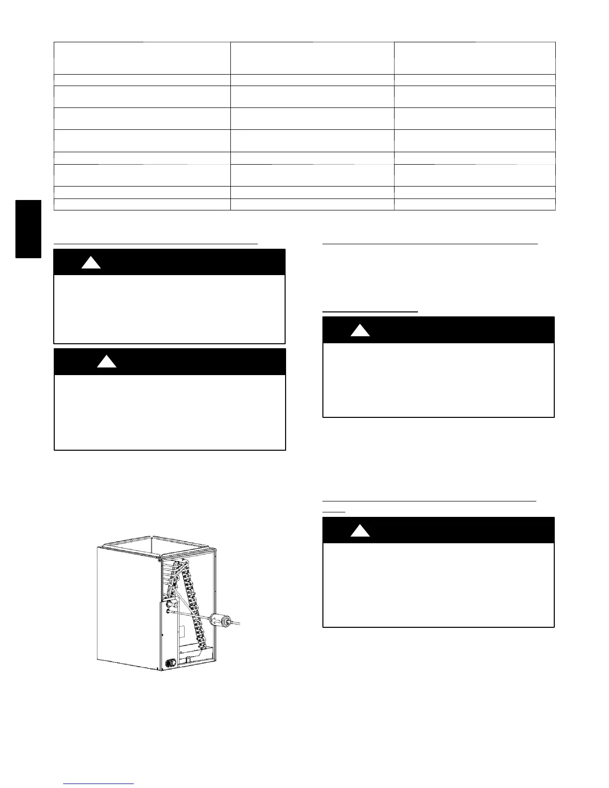
Refer to Fig. 5 and install filter drier as follows:
1. Braze 5 -- in. liquid tube to the indoor coil.
2. Wrap filter drier with damp cloth.
3. Braze filter drier to above 5” liquid tube. Flow arrow
must point towards indoor coil.
4. Connect and braze liquid refrigerant tube to the filter drier .
A05178
Fig. 5 --- Liquid Line Filter Drier
REFRIGERANT TUBING CONNECTION
OUTDOOR
Co n n ect vap o r tub e to fitting o n o u tdoor unit vapor service
valv es (see Tab le 1 .) C o n nect an d b raze th e 3/8 ” co u plin g
(provided with the filter drier) to the liquid service valve and
con nect an d braze th e liqui d tu b ing to the oth er en d o f th is
coupling. Use refrigerant grade tubing.
SWEAT
CONNECTION
CAUTION
!
UNIT DAMAGE HAZARD
Failure to follow this caution may result in equipment
damage or improper operation.
Service valves must be wrapped in a heat-- sinking
material such as a wet cloth.
Service valves are closed from factory and ready for brazing.
After wrapping service valve with a wet cloth, braze sweat
connections using industry accep ted m ethods and materials.
Consult local code requirements. Refrigerant tubing and indoor
coil are now ready for leak testing. This check should include all
field and factory joints.
EVACUATE REFRIGERANT TUBING AND
INDOOR
COIL
CAUTION
!
UNIT DAMAGE HAZARD
Failure to follow this caution may result in equipment
damage or improper operation.
Never use the system compressor as a vacuum pump.
Refrigerant tubes and indoor coil should be evacuated using the
recommended deep vacuum method of 500 microns. An alternate
triple ev acuatio n meth od m ay be u sed if th e d eep v acuu m
procedure is not followed.
IMPORTANT: Always break a vacuum with dry nitrogen.
163A / 165A