Manufacturer reserves the right to discontinue, or change at any time, specifications or designs without notice and without incurring obligations.
Catalog No. 04-53581021-01 Printed in U.S.A. Form SM581J-17-28-02 Pg 1 12-19 Replaces: SM581J-17-28-01
Service and Maintenance Instructions
CONTENTS
SAFETY CONSIDERATIONS . . . . . . . . . . . . . . . . . . . . . .1
UNIT ARRANGEMENT AND ACCESS . . . . . . . . . . . . . .2
General . . . . . . . . . . . . . . . . . . . . . . . . . . . . . . . . . . . . . . . . . .2
Routine Maintenance. . . . . . . . . . . . . . . . . . . . . . . . . . . . . . .3
SUPPLY FAN (BLOWER) SECTION . . . . . . . . . . . . . . . .4
Supply Fan Assembly . . . . . . . . . . . . . . . . . . . . . . . . . . . . . .4
Belt . . . . . . . . . . . . . . . . . . . . . . . . . . . . . . . . . . . . . . . . . . . . .4
TWO-SPEED INDOOR FAN MOTOR SYSTEM:
2-SPEED FAN WITH VARIABLE FREQUENCY
DRIVE (VFD) . . . . . . . . . . . . . . . . . . . . . . . . . . . . . . . . . .5
Two-Speed Indoor Fan Motor System. . . . . . . . . . . . . . . . .5
Identifying Factory Option . . . . . . . . . . . . . . . . . . . . . . . . . .6
Unit Installation with 2-Speed Indoor Fan Motor Option.6
ADDITIONAL VFD INSTALLATION AND
TROUBLESHOOTING . . . . . . . . . . . . . . . . . . . . . . . . . .6
MOTOR . . . . . . . . . . . . . . . . . . . . . . . . . . . . . . . . . . . . . . . . .6
Replacing the Motor . . . . . . . . . . . . . . . . . . . . . . . . . . . . . . .6
Changing Fan Wheel Speed by Changing Pulleys . . . . . . .7
CONDENSER COIL SERVICE . . . . . . . . . . . . . . . . . . . . .7
Round Tube Plate Fin (RTPF) Condenser Coil . . . . . . . . .7
Recommended Condenser Coil Maintenance and
Cleaning . . . . . . . . . . . . . . . . . . . . . . . . . . . . . . . . . . . . . . .7
EVAPORATOR COILS . . . . . . . . . . . . . . . . . . . . . . . . . . . .8
Evaporator Coil . . . . . . . . . . . . . . . . . . . . . . . . . . . . . . . . . . .8
Coil Maintenance and Cleaning Recommendation . . . . . .8
Evaporator Coil Metering Devices. . . . . . . . . . . . . . . . . . . .9
Refrigerant System Pressure Access Ports . . . . . . . . . . . . .9
PERFECT HUMIDITY ADAPTIVE DEHUMIDIFICA-
TION SYSTEM. . . . . . . . . . . . . . . . . . . . . . . . . . . . . . . .10
Perfect Humidity Modes . . . . . . . . . . . . . . . . . . . . . . . . . . .10
Perfect Humidity System Components . . . . . . . . . . . . . . .10
Subcooler/Reheat Coil. . . . . . . . . . . . . . . . . . . . . . . . . . . . .11
Operating Sequences . . . . . . . . . . . . . . . . . . . . . . . . . . . . . .11
THERMOSTATIC EXPANSION VALVE (TXV). . . . . .15
TXV Operation . . . . . . . . . . . . . . . . . . . . . . . . . . . . . . . . . .15
Replacing TXV. . . . . . . . . . . . . . . . . . . . . . . . . . . . . . . . . . .16
Refrigerant System Pressure Access Ports . . . . . . . . . . . .16
PURON® (R-410A) REFRIGERANT. . . . . . . . . . . . . . . .16
Refrigerant Charge . . . . . . . . . . . . . . . . . . . . . . . . . . . . . . .16
COOLING CHARGING CHARTS. . . . . . . . . . . . . . . . . .18
COMPRESSORS. . . . . . . . . . . . . . . . . . . . . . . . . . . . . . . . .22
Lubrication. . . . . . . . . . . . . . . . . . . . . . . . . . . . . . . . . . . . . .22
Replacing the Compressor . . . . . . . . . . . . . . . . . . . . . . . . .22
Filter Drier . . . . . . . . . . . . . . . . . . . . . . . . . . . . . . . . . . . . . .22
Adjusting the Condenser-Fan. . . . . . . . . . . . . . . . . . . . . . .22
TROUBLESHOOTING COOLING SYSTEM . . . . . . . .22
Troubleshooting Cooling System . . . . . . . . . . . . . . . . . . . .22
CONVENIENCE OUTLETS . . . . . . . . . . . . . . . . . . . . . . .24
Non-Powered Type . . . . . . . . . . . . . . . . . . . . . . . . . . . . . . .24
Unit-Powered Type . . . . . . . . . . . . . . . . . . . . . . . . . . . . . . .24
Wet in Use Convenience Outlet Cover. . . . . . . . . . . . . . . .24
Duty Cycle . . . . . . . . . . . . . . . . . . . . . . . . . . . . . . . . . . . . . .24
GFCI Maintenance . . . . . . . . . . . . . . . . . . . . . . . . . . . . . . .24
Fuse On Powered Type . . . . . . . . . . . . . . . . . . . . . . . . . . . . 25
Using Unit-Mounted Convenience Outlets . . . . . . . . . . . . 25
Installing a Weatherproof Cover . . . . . . . . . . . . . . . . . . . . 25
SMOKE DETECTORS . . . . . . . . . . . . . . . . . . . . . . . . . . . 25
System. . . . . . . . . . . . . . . . . . . . . . . . . . . . . . . . . . . . . . . . . . 25
Controller. . . . . . . . . . . . . . . . . . . . . . . . . . . . . . . . . . . . . . . 25
Sensor . . . . . . . . . . . . . . . . . . . . . . . . . . . . . . . . . . . . . . . . . . 26
Smoke Detector Locations . . . . . . . . . . . . . . . . . . . . . . . . . 26
FIOP Smoke Detector Wiring and Response . . . . . . . . . . 28
Sensor and Controller Tests. . . . . . . . . . . . . . . . . . . . . . . . 29
Detector Cleaning . . . . . . . . . . . . . . . . . . . . . . . . . . . . . . . . 30
INDICATORS . . . . . . . . . . . . . . . . . . . . . . . . . . . . . . . . . . . 30
Normal State . . . . . . . . . . . . . . . . . . . . . . . . . . . . . . . . . . . . 30
Alarm State . . . . . . . . . . . . . . . . . . . . . . . . . . . . . . . . . . . . . 30
Troubleshooting. . . . . . . . . . . . . . . . . . . . . . . . . . . . . . . . . . 31
PROTECTIVE DEVICES . . . . . . . . . . . . . . . . . . . . . . . . . 31
Compressor Protection . . . . . . . . . . . . . . . . . . . . . . . . . . . . 31
Supply (Indoor) Fan Motor Protection . . . . . . . . . . . . . . . 31
Control Circuit, 24-v. . . . . . . . . . . . . . . . . . . . . . . . . . . . . . 32
RTU-OPEN CONTROL SYSTEM . . . . . . . . . . . . . . . . . . 32
GAS HEATING SYSTEM . . . . . . . . . . . . . . . . . . . . . . . . . 32
General . . . . . . . . . . . . . . . . . . . . . . . . . . . . . . . . . . . . . . . . . 32
Fuel Types and Pressures . . . . . . . . . . . . . . . . . . . . . . . . . . 32
Flue Gas Passageways. . . . . . . . . . . . . . . . . . . . . . . . . . . . . 33
Combustion-Air Blower . . . . . . . . . . . . . . . . . . . . . . . . . . . 33
Burners and Igniters . . . . . . . . . . . . . . . . . . . . . . . . . . . . . . 34
Gas Valve . . . . . . . . . . . . . . . . . . . . . . . . . . . . . . . . . . . . . . . 37
ECONOMI$ER SYSTEMS . . . . . . . . . . . . . . . . . . . . . . . . 44
EconoMi$er IV Standard Sensors . . . . . . . . . . . . . . . . . . . 48
EconoMi$er® X (Factory Option). . . . . . . . . . . . . . . . . . . 54
PRE-START-UP/START-UP . . . . . . . . . . . . . . . . . . . . . . 67
START-UP, GENERAL . . . . . . . . . . . . . . . . . . . . . . . . . . . 67
Unit Preparation . . . . . . . . . . . . . . . . . . . . . . . . . . . . . . . . . 67
Additional Installation/Inspection . . . . . . . . . . . . . . . . . . . 67
FASTENER TORQUE VALUES . . . . . . . . . . . . . . . . . . . 69
APPENDIX A — MODEL NUMBER
NOMENCLATURE . . . . . . . . . . . . . . . . . . . . . . . . . . . . 70
APPENDIX B — PHYSICAL DATA . . . . . . . . . . . . . . . . 71
APPENDIX C — FAN PERFORMANCE . . . . . . . . . . . . 75
APPENDIX D — WIRING DIAGRAMS . . . . . . . . . . . . . 83
APPENDIX E — MOTORMASTER SENSOR
LOCATIONS . . . . . . . . . . . . . . . . . . . . . . . . . . . . . . . . . 94
START-UP CHECKLIST . . . . . . . . . . . . . . . . . . . . . . CL-1
SAFETY CONSIDERATIONS
Installation and servicing of air-conditioning equipment can be
hazardous due to system pressure and electrical components. Only
trained and qualified service personnel should install, repair, or
service air-conditioning equipment.
Untrained personnel can perform basic maintenance functions of
cleaning coils and filters and replacing filters. All other operations
should be performed by trained service personnel. When working
on air-conditioning equipment, observe precautions in the litera-
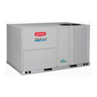
Preferred Series™
581J*17-28
Gas Heat/Electric Cooling
with Puron
®
(R-410A) Refrigerant


