4
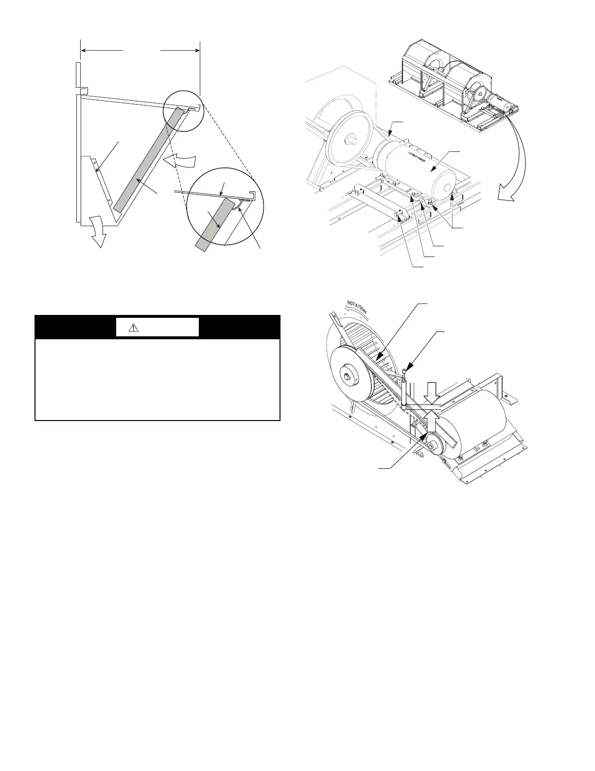
Fig. 3 — Inlet Air Screen Installation
SUPPLY FAN (BLOWER) SECTION
Supply Fan Assembly
The supply fan system consists of two forward-curved centrifugal
blower wheels mounted on a solid blower shaft that is supported
by two greaseable pillow block concentric bearings. A fixed-pitch
driven fan pulley is attached to the fan shaft and an adjustable-
pitch driver pulley is mounted on the motor. The pulleys are con-
nected using a V-belt. See Fig. 4.
Belt
Check the belt condition and tension quarterly. Inspect the belt for
signs of cracking, fraying or glazing along the inside surfaces.
Check belt tension by using a spring-force tool, such as Brown-
ing’s “Belt Tension Checker” (P/N: 1302546 or equivalent tool);
tension should be 6 lb at a
5
/
8
-in. (1.6 cm) deflection when mea-
sured at the centerline of the belt span. This point is at the center of
the belt when measuring the distance between the motor shaft and
the blower shaft. See Fig. 5.
NOTE: Without the spring-tension tool, place a straight edge
across the belt surface at the pulleys, then push down on the belt at
mid-span using one finger until a
1
/
2
-in. (1.3 cm) deflection is
reached.
Fig. 4 — Belt Drive Motor Mounting
Fig. 5 — Checking Blower Motor Belt Tension
ADJUSTING THE BELT TENSION
Use the following steps to adjust the V-belt tension. See Fig. 4.
1. Loosen the four motor mounting nuts that attach the motor
to the blower rail.
2. Loosen the two jackbolt locking nuts beneath the motor
mounting plate. Turn the jackbolt locking nut counter-
clockwise to loosen.
3. Turn the jack bolts counterclockwise to loosen and clock-
wise to tighten.
4. Adjust the V-belt for proper tension.
5. Ensure the fan shaft and the motor shaft are parallel prior
to tightening motor mounting nuts. See Fig. 6.
6. Make adjustments as necessary.
7. Tighten the four motor mounting nuts.
8. Check the V-belt tension. Make adjustments as necessary.
9. Re-tighten the four motor mounting nuts.
10. Tighten both jackbolt locking nuts securely.
CAUTION
ELECTRICAL SHOCK HAZARD
Failure to follow this warning could cause personal injury or
death.
Before performing service or maintenance operations on the
fan system, shut off all unit power and lockout/tag-out the unit
disconnect switch. DO NOT reach into the fan section with
power still applied to unit.
17 1/4”
DIVIDER
BAROMETRIC
RELIEF
CLEANABLE
ALUMINUM
FILTER
FILTER
HOOD
FILTER
CLIP
OUTSIDE
AIR
MOTOR
V-BELT
MOTOR ADJUSTMENT
BOLTS (4)
JACKBOLT LOCKING NUT (2)
MOTOR MOUNTING PLATE
JACKBOLT (2)
BROWNING BELT
TENSION CHECKER
STRAIGHTEDGE
1/2”
(1.3 cm)
BELT
DEFLECTION