32
The High Static option supply fan motor is equipped with a pilot-
circuit Thermik
1
combination overtemperature/overcurrent pro-
tection device. This device resets automatically. Do not bypass
this switch to correct trouble. Determine the cause and correct it.
The Thermik device is a snap-action overtemperature protection
device that is embedded in the motor windings. The Thermik de-
vice can be identified by two blue wires extending out of the mo-
tor control box. It is a pilot-circuit device that is wired into the
unit’s 24-v control circuit. When this switch reaches its trip set-
point, it opens the 24-v control circuit and causes all unit operation
to cease. This device resets automatically when the motor wind-
ings cool. Do not bypass this switch to correct trouble. Determine
the cause and correct it.
The External Overload Breaker is an overcurrent device used on
motors with a horsepower rating of 4.7 hp or greater. This is a spe-
cially-calibrated circuit breaker that is UL recognized as a motor
overload controller. When the current to the motor exceeds the cir-
cuit breaker setpoint, the device opens all motor power leads to the
motor shutting the motor down. Reset requires a manual reset at
the overload switch. This device (designated IFCB) is located on
the side of the supply fan housing, behind the fan access panel.
The Must Hold and Must Trip values are listed on the side of the
External Overload Breaker.
TROUBLESHOOTING SUPPLY FAN MOTOR OVER-
LOAD TRIPS
The supply fan used in 581J units is a forward-curved centrifugal
wheel. At a constant wheel speed, this wheel has a characteristic
that causes the fan shaft load to DECREASE when the static pres-
sure in the unit-duct system increases and to INCREASE when
the static pressure in the unit-duct system decreases (and fan air-
flow rate increases). Motor overload conditions typically develop
when the unit is operated with an access panel removed, with un-
finished duct work, in an economizer-open mode, or a leak devel-
ops in the duct system that allows a bypass back to unit return
opening.
CONDENSER FAN MOTOR PROTECTION
The condenser fan motor is internally protected against over
temperature.
Control Circuit, 24-v
The control circuit is protected against overcurrent conditions by a
circuit breaker mounted on control transformer TRAN. Reset is
manual.
RTU-OPEN CONTROL SYSTEM
For details on operating 581J units equipped with the factory-in-
stalled RTU Open controller, refer to the “Factory-Installed RTU
Open Multi-Protocol Controller Control, Start-Up, Operation and
Troubleshooting” manual.
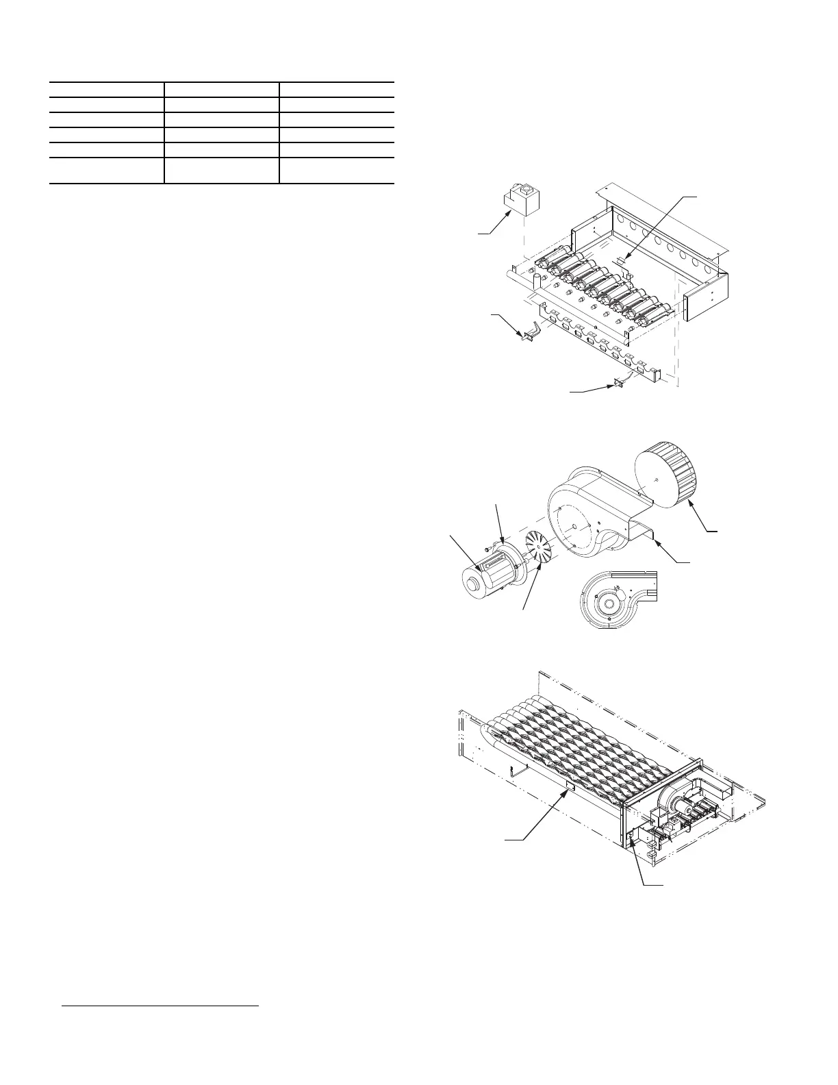
GAS HEATING SYSTEM
General
The heat exchanger system consists of a gas valve feeding multi-
ple inshot burners off a manifold. The burners fire into matching
primary tubes. The tubes exit into the collector box, the into the in-
duced draft fan wheel inlet. The induced fan wheel discharges into
a flue passage and flue gases exit out a flue hood on the side of the
unit. The induced draft fan motor includes a Hall Effect sensor cir-
cuit that confirms adequate wheel speed through the Integrated
Gas Control (IGC) board. Safety switches include a Rollout
Switch mounted at the top of the burner compartment. A limit
switch is mounted through the side of the fan deck over the tubes.
The vestibule plate faces the tubes. See Fig. 38-40.
Fig. 38 — Burner Section Details
Fig. 39 — Inducer Assembly
Fig. 40 — Limit Switch Locations
Fuel Types and Pressures
NATURAL GAS
The 581J unit is factory-equipped for use with natural gas (NG)
fuel at elevation under 2000 ft (610 m). See section Orifice Re-
placement on page 37 for information in modifying this unit for
installation at elevations above 2000 ft (610 m).
Table 8 — Overcurrent Device Type
MOTOR SIZE (bhp) OVERLOAD DEVICE RESET
1.7 Internal Linebreak Automatic
2.4 Internal Linebreak Automatic
2.9 Thermik Automatic
3.7 Thermik Automatic
4.7
External
(Circuit Breaker)
Manual
1. Thermik is a trademark of Thermik Geratebau GmbH.
ROLLOUT
SWITCH
GAS
VALVE
SPARK
IGNITER
FLAME
SENSOR
CAPACITOR
INDUCER
HOUSING
INDUCER
WHEEL
INDUCER
COOLING FAN
INDUCER
MOTOR
LIMIT
SWITCH FOR
SIDESHOT
LIMIT SWITCH
FOR DOWNSHOT
 Loading...


