25
3. Repair ground wire connections as needed and correct line
phasing.
4. Press the RESET button to clear the tripped condition.
Fuse On Powered Type
The factory fuse is a Bussmann
1
“Fusetron” T-15, non-renewable
screw-in (Edison base) type plug fuse.
Using Unit-Mounted Convenience Outlets
Units with unit-mounted convenience outlet circuits will often re-
quire that two disconnects be opened to de-energize all power to
the unit. Treat all units as electrically energized until the conve-
nience outlet power is also checked and de-energization is con-
firmed. Observe National Electrical Code Article 210, Branch Cir-
cuits, for use of convenience outlets. Always use a volt meter to
verify no voltage is present at the GFIC receptacles before work-
ing on unit.
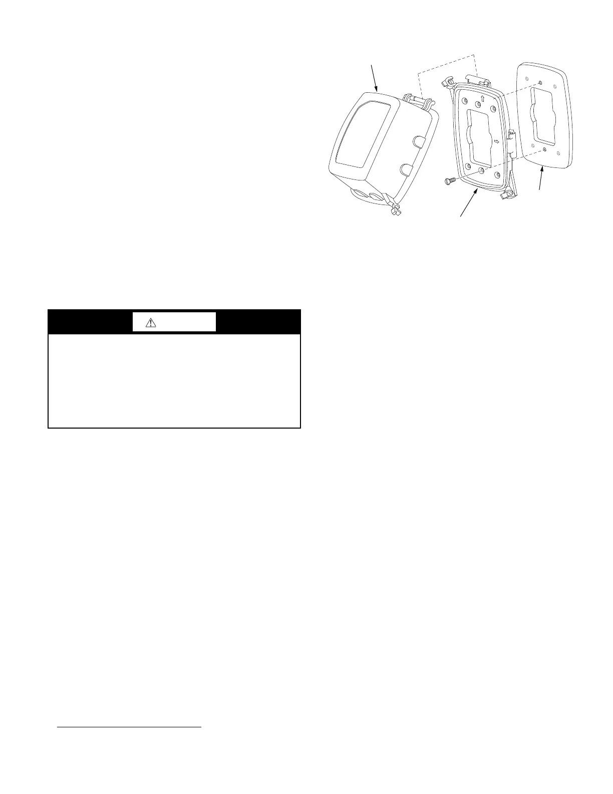
Installing a Weatherproof Cover
A weatherproof while-in-use cover for the factory-installed conve-
nience outlets is now required by UL standards. This cover cannot
be factory-mounted due to its depth. The cover must be installed at
unit installation. For shipment, the convenience outlet is covered
with a blank cover plate.
The weatherproof cover kit is shipped in the unit’s control box.
The kit includes the hinged cover, a backing plate and gasket.
1. Remove the blank cover plate at the convenience outlet.
Discard the blank cover.
2. Loosen the two screws at the GFCI duplex outlet, until
approximately
1
/
2
-in. (13 mm) under screw heads is
exposed.
3. Press the gasket over the screw heads. Slip the backing
plate over the screw heads at the keyhole slots and align
with the gasket; tighten the two screws until snug. Do not
over-tighten.
4. Mount the weatherproof cover to the backing plate as
shown in Fig. 28.
5. Remove two slot fillers in the bottom of the cover allow-
ing service tool cords to exit the cover.
6. Check cover installation for full closing and latching.
Fig. 28 — Weatherproof Cover Installation
SMOKE DETECTORS
Smoke detectors are available as factory-installed options on 581J
models. Smoke detectors can be specified for supply air only, for
return air with or without economizer, or in combination of supply
air and return air. Return-air smoke detectors are arranged for ver-
tical return configurations only. All components necessary for op-
eration are factory-provided and mounted. The unit is factory-con-
figured for immediate smoke detector shutdown operation. Addi-
tional wiring or modifications to unit terminal board can be
necessary to complete the unit and smoke detector configuration
to meet project requirements.
System
The smoke detector system consists of a four-wire controller
(HT28TZ001) and one or two sensors (HT50TZ001). Its primary
function is to shut down the rooftop unit in order to prevent smoke
from circulating throughout the building. It is not to be used as a
life saving device.
Controller
The controller includes a controller housing, a printed circuit
board, and a clear plastic cover. See Fig. 29. The controller can be
connected to one or two compatible duct smoke sensors. The clear
plastic cover is secured to the housing with a single captive screw
for easy access to the wiring terminals. The controller has three
LEDs: Power, Trouble and Alarm. A manual test/reset button is
located on the cover face.
1. Bussman and Fusetron are trademarks of Cooper Technologies
Company.
DANGER
ELECTRICAL SHOCK HAZARD
Failure to follow this warning will result in personal injury or
death.
Before performing service or maintenance operations on unit,
turn off main power switch to unit and install lock(s) and lock-
out tag(s). Ensure electrical service to rooftop unit agrees with
voltage and amperage listed on the unit rating plate. Unit may
have more than one power switch.
TOP
TOP
TOP
W
E
T
LO
C
AT
ION
S
WE
T
L
O
C
A
T
I
O
NS
COVER - WHILE-IN-USE
WEATHERPROOF
BASEPLATE FOR
GFCI RECEPTACLE
GASKET
GFCI RECEPTACLE
NOT INCLUDED

 Loading...


