33
Gas line pressure entering the unit’s main gas valve must be within
specified ranges. See Table 9. Adjust unit gas regulator valve as
required or consult local gas utility.
Manifold pressure is factory-adjusted for NG fuel use. Adjust as
required to obtain best flame characteristic. See Table 10.
LIQUID PROPANE
Accessory packages are available for field-installation that will
convert the 581J unit to operate with liquid propane (LP) fuels.
These kits include new orifice spuds, new springs for gas valves
and a supply line low pressure switch. See section on Orifice Re-
placement on page 37 for details on orifice size selections.
Fuel line pressure entering unit gas valve must remain within
specified range. See Table 11.
Manifold pressure for LP fuel use must be adjusted to specified
range. See Table 12. Follow instructions in the accessory kit to
make initial readjustment.
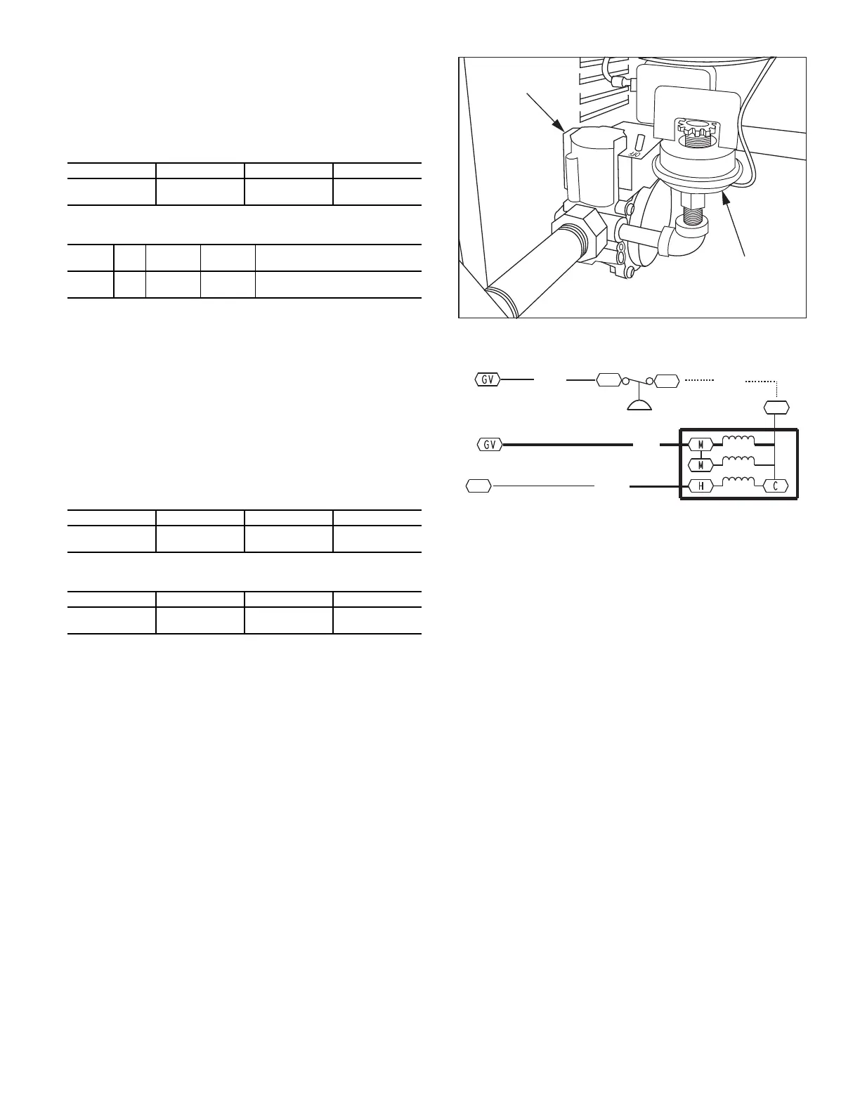
SUPPLY PRESSURE SWITCH
The LP conversion kit includes a supply low pressure switch. The
switch contacts (from terminal C to terminal NO [Normally
Open]) will open the gas valve power whenever the supply line
pressure drops below the setpoint. See Fig. 41 and 42. The switch,
HK02LB008, opens contacts on pressure “fall” at 7.2 in. wg
± 0.70 in. wg. Contacts close on pressure rise above 10.2 in. wg. If
the low pressure remains open for 15 minutes during a call for
heat, the IGC circuit will initiate a Ignition Fault (5 flashes) lock-
out. Reset of the low pressure switch is automatic on rise in supply
line pressure. Reset of the IGC requires a recycle of unit power af-
ter the low pressure switch has closed.
LIMIT SWITCH
Remove blower access panel. Limit switch is located on the fan
deck for sideshot units and on the vestibule plate for downshot
units. See Fig. 40.
This switch also prevents operation when the propane tank level is
low which can result in gas with a high concentration of impuri-
ties, additives, and residues that have settled to the bottom of the
tank. Operation under these conditions can cause harm to the heat
exchanger system. Contact your fuel supplier if this condition is
suspected.
Fig. 41 — LP Low Pressure Switch (installed) for 581J*D
Fig. 42 — LP Supply Line Low Pressure Switch Wiring
Flue Gas Passageways
To inspect the flue collector box and upper areas of the heat
exchanger:
1. Remove the combustion blower wheel and motor assem-
bly according to directions in Combustion-Air Blower sec-
tion. See Fig. 43.
2. Remove the flue cover to inspect the heat exchanger.
3. Clean all surfaces as required using a wire brush.
Combustion-Air Blower
Clean periodically to assure proper airflow and heating efficiency.
Inspect blower wheel every fall and periodically during heating
season. For the first heating season, inspect blower wheel bi-
monthly to determine proper cleaning frequency.
To access burner section, open the heater access door below the
indoor fan panel.
To inspect blower wheel, shine a flashlight into draft hood open-
ing. If cleaning is required, remove motor and wheel as follows:
1. Remove the seven screws attaching the induced-draft
motor housing to the vestibule plate. See Fig. 43.
2. The blower wheel can be cleaned at this point. If additional
cleaning is required, continue with Steps 3 through 5.
3. Remove the blower from the motor shaft, by loosening
two setscrews.
4. Remove the motor by removing the four screws that hold
the motor to mounting plate. Remove the motor cooling
fan by removing one setscrew.
5. Remove the nuts that hold the motor to the mounting plate.
6. To reinstall, reverse the procedure outlined above.
Table 9 — Natural Gas Supply Line Pressure Ranges
UNIT MODEL UNIT SIZE MIN MAX
581J ALL
4.0 in. wg
(996 Pa)
13.0 in. wg
(3240 Pa)
Table 10 — Natural Gas Manifold Pressure Ranges
UNIT
MODEL
UNIT
SIZE
HIGH
FIRE
LOW
FIRE
RANGE
581J All 3.0 in. wg 2.0 in. wg
Reference MRT unit nameplate
for range ratings.
Table 11 — Liquid Propane Supply Line Pressure Ranges
UNIT MODEL UNIT SIZE MIN MAX
581J All
11.0 in. wg
(2740 Pa)
13.0 in. wg
(3240 Pa)
Table 12 — Liquid Propane Manifold Pressure Ranges
UNIT MODEL UNIT SIZE HIGH FIRE LOW FIRE
581J All
11.0 in. wg
(2740 Pa)
7.3 in. wg
(1820 Pa)
LP LOW PRESSURE
SWITCH
GAS VALVE
PNK
W2
TSTAT
GRA
BRN
IGC
J2-12
IGC
J2-11
BRN
C
NO
MGV
C
LP LPS
 Loading...


