28
Fig. 33 — Return-Air Sampling Tube Location in Unit with
Economizer
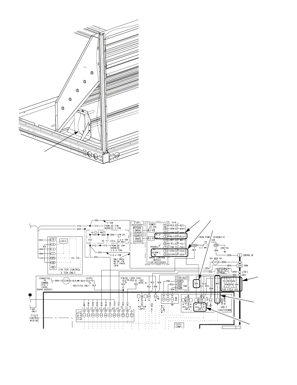
FIOP Smoke Detector Wiring and Response
All units: The FIOP smoke detector is configured to automatically
shut down all unit operations when a smoke condition is detected.
See Fig. 34 for smoke detector wiring.
HIGHLIGHT A
JMP 3 is factory-cut, transferring unit control to smoke detector.
HIGHLIGHT B
Smoke detector NC contact set will open on smoke alarm condi-
tion, de-energizing the ORN conductor.
HIGHLIGHT C
24-v power signal using the ORN lead is removed at Smoke De-
tector input on Central Terminal board (CTB); all unit operations
cease immediately.
RTU-OPEN CONTROLS
Unit operating functions (fan, cooling and heating) are terminated
as described above.
HIGHLIGHT D
On smoke alarm condition, the smoke detector NO Alarm contact
will close, supplying 24-v power to GRA conductor.
HIGHLIGHT E
GRA lead at Smoke Alarm input on LCTB provides 24-v signal to
FIOP DDC control.
RTU-OPEN
The 24-v signal is conveyed to the RTU-OPEN J1-10 input termi-
nal. This signal initiates the FSD sequence by the RTU-OPEN
control. FSD status is reported to connected BAS network.
USING REMOTE LOGIC
Five field use conductors are provided for additional annunciation
functions.
ADDITIONAL APPLICATION DATA
Refer to Factory-Installed Smoke Detectors for Small and Medi-
um Rooftop Units 2 to 25 Tons for discussions on additional con-
trol features of these smoke detectors, including multiple unit co-
ordination. See Fig. 34.
Fig. 34 — Typical Smoke Detector System Wiring
RETURN-AIR
SMOKE
DETECTOR
SENSOR
 Loading...


