48
* For single enthalpy control, the module compares outdoor enthalpy to
the ABCD set point.
† Power at N terminal determines Occupied/Unoccupied setting: 24 vac
(Occupied), no power (Unoccupied).
** Modulation is based on the supply-air sensor signal.
†† Modulation is based on the DCV signal.
*** Modulation is based on the greater of DCV and supply-air sensor
signals, between minimum position and either maximum position (DCV)
or fully open (supply-air signal).
††† Modulation is based on the greater of DCV and supply-air sensor
signals, between closed and either maximu m position (DCV) or fully
open (supply-air signal).
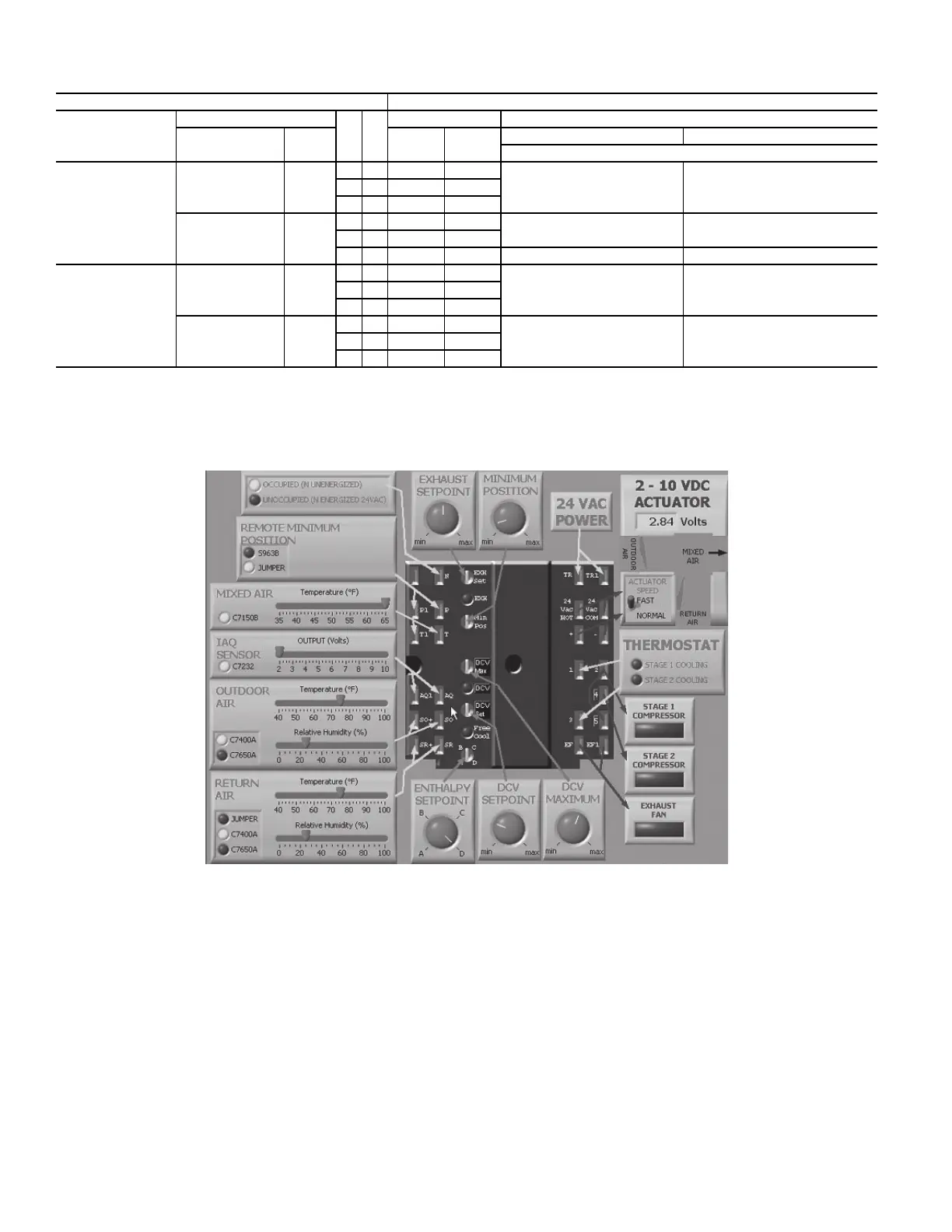
Fig. 60 — EconoMi$er IV Functional View
EconoMi$er IV Standard Sensors
Table 20 provides a summary of EconoMi$er IV. Troubleshooting
instructions are enclosed. A functional view of the EconoMi$er IV
system is shown in Fig. 60. Typical settings, sensor ranges, and
jumper positions are also shown. An EconoMi$er IV simulator
program is available from Bryant to help with EconoMi$er IV
training and troubleshooting.
OUTDOOR AIR TEMPERATURE (OAT) SENSOR
The outdoor air temperature sensor (HH57AC074) is a 10 to
20 mA device used to measure the outdoor-air temperature. The
outdoor-air temperature is used to determine when the
EconoMi$er IV can be used for free cooling. The sensor is facto-
ry-installed on the EconoMi$er IV in the outdoor airstream. (See
Fig. 61.) The operating range of temperature measurement is 40°F
to 100°F (4°C to 38°C). See Fig. 62.
SUPPLY AIR TEMPERATURE (SAT) SENSOR
The supply air temperature sensor is a 3 K thermistor located at
the inlet of the indoor fan. (See Fig. 61.) This sensor is factory in-
stalled. The operating range of temperature measurement is 0°F to
158°F (–18°C to 70°C).
The temperature sensor looks like an eyelet terminal with wires
running to it. The sensor is located in the “crimp end” and is sealed
from moisture.
Table 20 — EconoMi$er IV Input/Output Logic
INPUTS OUTPUTS
Demand
Controlled
Ventilation (DCV)
Enthalpy*
Y1 Y2
Compressor N Terminal†
Outdoor Return Stage 1 Stage 2
Occupied Unoccupied
Damper
Below set
(DCV LED off)
High (Free
Cooling LED off)
Low
On On On On
Minimum position ClosedOn Off On Off
Off Off Off Off
Low (Free
Cooling LED on)
High
On On On Off
Modulating** (between min.
position and full-open)
Modulating** (between closed
and full-open)
On Off Off Off
Off Off Off Off Minimum position Closed
Above set
(DCV LED on)
High (Free
Cooling LED off)
Low
On On On On
Modulating†† (between min.
position and DCV maximum)
Modulating†† (between closed
and DCV maximum)
On Off On Off
Off Off Off Off
Low (Free
Cooling LED on)
High
On On On Off
Modulating*** Modulating†††On Off Off Off
Off Off Off Off

 Loading...


