37
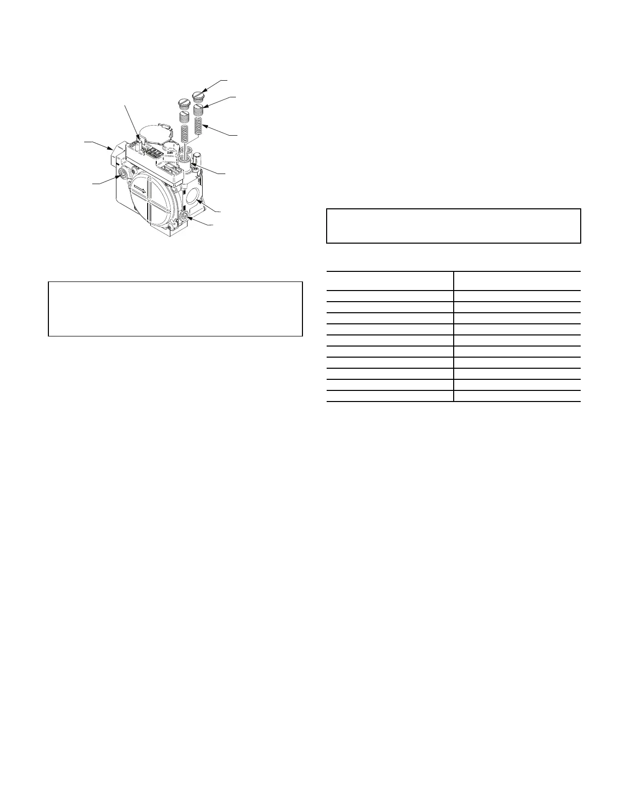
Gas Valve
All unit sizes are equipped with 2-stage gas valves. See Fig. 48 for
locations of adjustment screws and features on the gas valves.
Fig. 48 — Gas Valve
ADJUSTING GAS VALVE PRESSURE SETTINGS
CHECK UNIT OPERATION AND MAKE NECESSARY
ADJUSTMENTS
NOTE: Gas supply pressure at gas valve inlet must be within
specified ranges for fuel type and unit size. See Tables 9-12.
1. Shut off electrical power supplies to unit and install lock-
out tag.
2. Shut off manual gas shut off valve located on gas supply
line.
3. Remove manifold pressure tap plug from manifold and
connect pressure gage or manometer. See Fig. 46.
4. Turn on electrical supply.
5. Open manual shut off valve, then turn on unit main gas
valve.
6. Set room thermostat to call for heat. Verify high-stage heat
operation before attempting to adjust manifold pressure.
7. When main burners ignite, check all fittings, manifold,
and orifices for leaks.
8. Adjust high-stage pressure to specified setting by turning
the plastic adjustment screw clockwise to increase pres-
sure, counter-clockwise to decrease pressure.
9. Set room thermostat to call for low-stage heat. Adjust low-
stage pressure to specified setting.
10. Replace regulator cover screw(s) when finished.
11. With burner access panel removed, observe unit heating
operation in both high stage and low stage operation.
Observe burner flames to see if they are blue in appear-
ance, and that the flames are approximately the same for
each burner.
12. Turn off unit, close manual gas shut off valve, remove
pressure manometer and replace the
1
/
8
-in. pipe fitting on
the gas manifold. See Fig. 46.
BURNER IGNITION
Unit is equipped with a direct spark ignition 100% lockout system.
Integrated Gas Unit Controller (IGC) is located in the control box.
See Fig. 47. The IGC contains a self-diagnostic LED (light-emit-
ting diode). A single LED (see Fig. 50) on the IGC provides a vi-
sual display of operational or sequential problems when the power
supply is uninterrupted. When a break in power occurs, the IGC
will be reset, resulting in a loss of fault history, and the indoor
evaporator fan ON/OFF times will be reset. The LED error code
can be observed through the viewport. During servicing, refer to
the label on the control box cover or Table 13 for an explanation of
LED error code descriptions.
* A 3 second pause exists between LED error code flashes. If more
than one error code exists, all applicable codes will be displayed in
numerical sequence.
If lockout occurs, unit can be reset by interrupting power supply to
unit for at least 5 seconds.
ORIFICE REPLACEMENT
This unit uses orifice type LH32RFnnn (where nnn indicates ori-
fice reference size). When replacing unit orifices, order the neces-
sary parts through the Replacement Components Division (RCD).
See Table 14 for available orifice sizes. See Table 15 and Fig. 50
and 51 for IGC wiring and connections. See Tables 16 and 17 for
orifice sizes for Natural Gas and LP fuel usage at various eleva-
tions above sea level. Never drill or plug orifices for operation.
Check that each replacement orifice is tight at its threads into the
manifold pipe and that orifice projection does not exceed maxi-
mum value. See Fig. 44.
IMPORTANT: Leak check (using a mixture of soapy water
or leak detection fluid) all gas connections including the
main service connection, gas valve, gas spuds, and mani-
fold pipe plug. All leaks must be repaired before firing unit.
PLASTIC ADJUST
SCREW (2)
REGULATOR SPRING (2)
(PROPANE - WHITE
NATURAL - SILVER)
LOW STAGE
GAS PRESSURE
REGULATOR
ADJUSTMENT
MANIFOLD
PRESSURE TAP
INLET
PRESSURE TAP
ON/OFF
SWITCH
REGULATOR
COVER SCREW (2)
NPT INLET
NPT OUTLET
IMPORTANT: Refer to Troubleshooting Tables 18 and 19
for additional information.
Table 13 — LED Error Code Description*
LED INDICATION
ERROR CODE
DESCRIPTION
ON Normal Operation
OFF Hardware Failure
2 Flashes Limit Switch Fault
3 Flashes Flame Sense Fault
4 Flashes 4 Consecutive Limit Switch Faults
5 Flashes Ignition Lockout Fault
6 Flashes Induced-Draft Motor Fault
7 Flashes Rollout Switch Fault
8 Flashes Internal Control Fault
9 Flashes Software Lockout
LEGEND
LED — Light Emitting Diode