30
Fig. 35 — Remote Test/Reset Station Connections
DIRTY SENSOR TEST USING AN SD-TRK4
1. Turn the key switch to the RESET/TEST position for
two seconds.
2. Verify that the test/reset station’s Trouble LED flashes.
Detector Cleaning
CLEANING THE SMOKE DETECTOR
Clean the duct smoke sensor when the Dirty LED is flashing con-
tinuously or sooner if conditions warrant.
1. Disconnect power from the duct detector, then remove the
sensor’s cover. See Fig. 36.
2. Using a vacuum cleaner, clean compressed air, or a soft
bristle brush, remove loose dirt and debris from inside the
sensor housing and cover.
Use isopropyl alcohol and a lint-free cloth to remove dirt
and other contaminants from the gasket on the sensor’s
cover.
3. Squeeze the retainer clips on both sides of the optic hous-
ing then lift the housing away from the printed circuit
board.
4. Gently remove dirt and debris from around the optic plate
and inside the optic housing.
5. Replace the optic housing and sensor cover.
6. Connect power to the duct detector, then perform a sensor
alarm test.
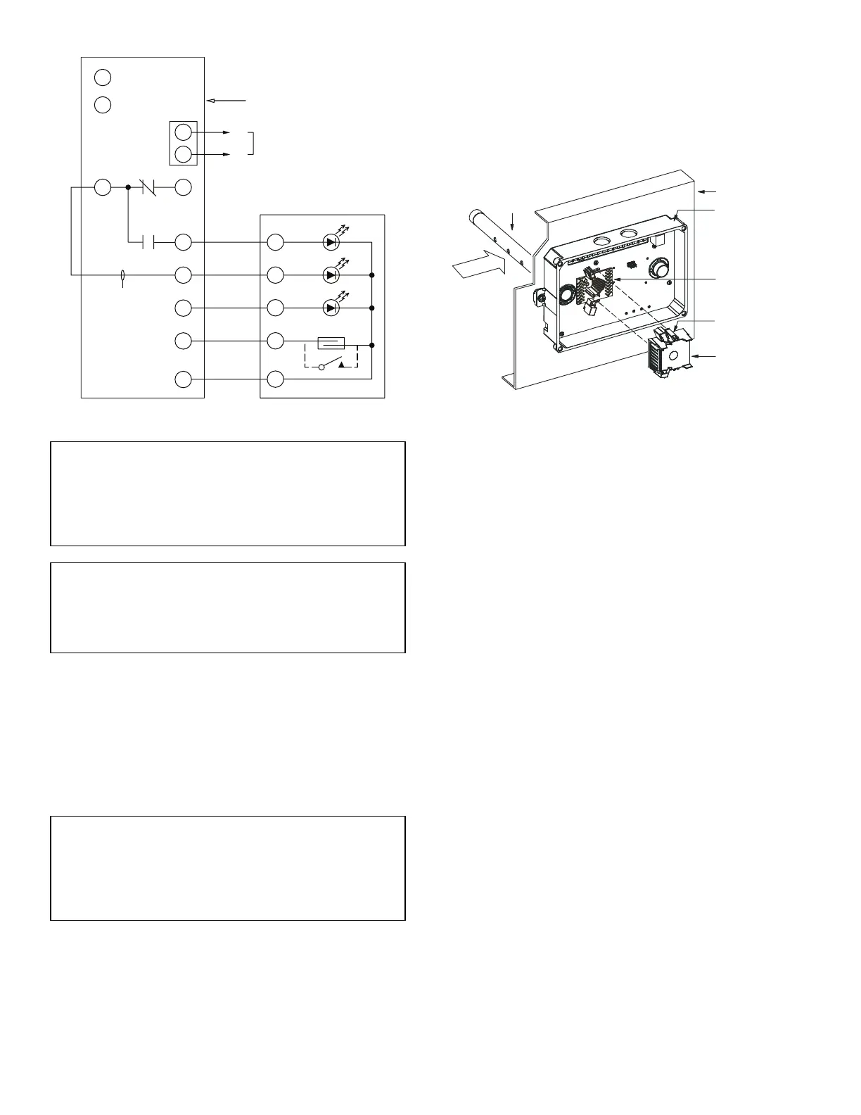
Fig. 36 — Sensor Cleaning Diagram
INDICATORS
Normal State
The smoke detector operates in the normal state in the absence of
any trouble conditions and when its sensing chamber is free of
smoke. In the normal state, the Power LED on both the sensor and
the controller are on and all other LEDs are off.
Alarm State
The smoke detector enters the alarm state when the amount of
smoke particulate in the sensor’s sensing chamber exceeds the
alarm threshold value. See Table 7.
Upon entering the alarm state:
• The sensor’s Alarm LED and the controller’s Alarm LED
turn on.
• The contacts on the controller’s two auxiliary relays switch
positions.
• The contacts on the controller’s alarm initiation relay
close.
• The controller’s remote alarm LED output is activated
(turned on).
• The controller’s high impedance multiple fan shutdown
control line is pulled to ground Trouble state.
The SuperDuct™ duct smoke detector enters the trouble state un-
der the following conditions:
• A sensor’s cover is removed and 20 minutes pass before it
is properly secured.
• A sensor’s environmental compensation limit is reached
(100% dirty).
• A wiring fault between a sensor and the controller is detected.
An internal sensor fault is detected upon entering the trouble state:
• The contacts on the controller’s supervisory relay switch
positions. (See Fig. 37.)
• If there is a sensor fault, the sensor’s Trouble LED and the
controller’s Trouble LED will turn on.
• If 100% dirty, the sensor’s Dirty LED turns on and the
controller’s Trouble LED flashes continuously.
• If there is a wiring fault between a sensor and the control-
ler, the controller’s Trouble LED turns on but not the sen-
sor’s LED.
IMPORTANT: Failure to follow this NOTICE can result in
an unnecessary evacuation of the facility.
If the test/reset station’s key switch is left in the RESET/
TEST position for longer than seven seconds, the detector
will automatically go into the alarm state and activate all
automatic alarm responses.
IMPORTANT: Failure to follow this NOTICE can result in
an unnecessary evacuation of the facility.
Holding the test magnet to the target area for longer than
seven seconds will put the detector into the alarm state and
activate all automatic alarm responses.
IMPORTANT: Failure to follow this NOTICE can result in
an unnecessary evacuation of the facility.
If the smoke detector is connected to a fire alarm system,
first notify the proper authorities that the detector is under-
going maintenance then disable the relevant circuit to avoid
generating a false alarm.
1
12
14
13
19
15
2
20
3
RESET/TEST
Trouble
POWER
ALARM
SUPERVISION RELAY
CONTACTS [3]
5
4
1
3
2
SD-TRK4
2
1
TB3
18 VDC (-)
18 VDC (-)
AUXILIARY
EQUIPMENT
+
−
WIRE MUST BE
ADDED BY
INSTALLER
SMOKE DETECTOR
CONTROLLER
HVAC DUCT
SAMPLING
TUBE
RETAINER
CLIP
OPTIC
PLATE
OPTIC
HOUSING
SENSOR
HOUSING
AIRFLOW