57
5. Press the ▲ button to increase (change) the displayed
parameter value.
6. Press the ▼ button to decrease (change) the displayed
parameter value.
NOTE: When values are displayed, pressing and holding the
▲ or ▼ button causes the display to automatically increment or
decrement.
1. Press the (Enter) button to accept the displayed value
and store it in nonvolatile RAM. “CHANGE STORED”
displays.
2. Press the (Enter) button to return to the current menu
parameter.
3. Press the (Menu Up/Exit) button to return to the previ-
ous menu.
Menu Structure
Table 27 illustrates the complete hierarchy of menus and parame-
ters for the EconoMi$er
®
X system.
The Menus in display order are:
•STATUS
• SETPOINTS
• SYSTEM SETUP
• ADVANCED SETUP
•CHECKOUT
•ALARMS
NOTE: Some parameters in the menus use the letters MA or
MAT, indicating a mixed air temperature sensor location before
the cooling coil. This unit application has the control sensor
located after the cooling coil, in the fan section, where it is desig-
nated as (Cooling) Supply Air Temperature or SAT sensor.
SETUP AND CONFIGURATION
Before being placed into service, the W7220 Economizer module
must be set up and configured for the installed system.
The setup process uses a hierarchical menu structure that is easy to
use. Press the ▲ and ▼ arrow buttons to move forward and back-
ward through the menus and press the button to select and confirm
setup item changes.
Time-Out and Screensaver
When no buttons have been pressed for 10 minutes, the LCD
displays a screen saver, which cycles through the Status items.
Each Status items displays in turn and cycles to the next item af-
ter 5 seconds.
IMPORTANT: During setup, the economizer module is
live at all times.
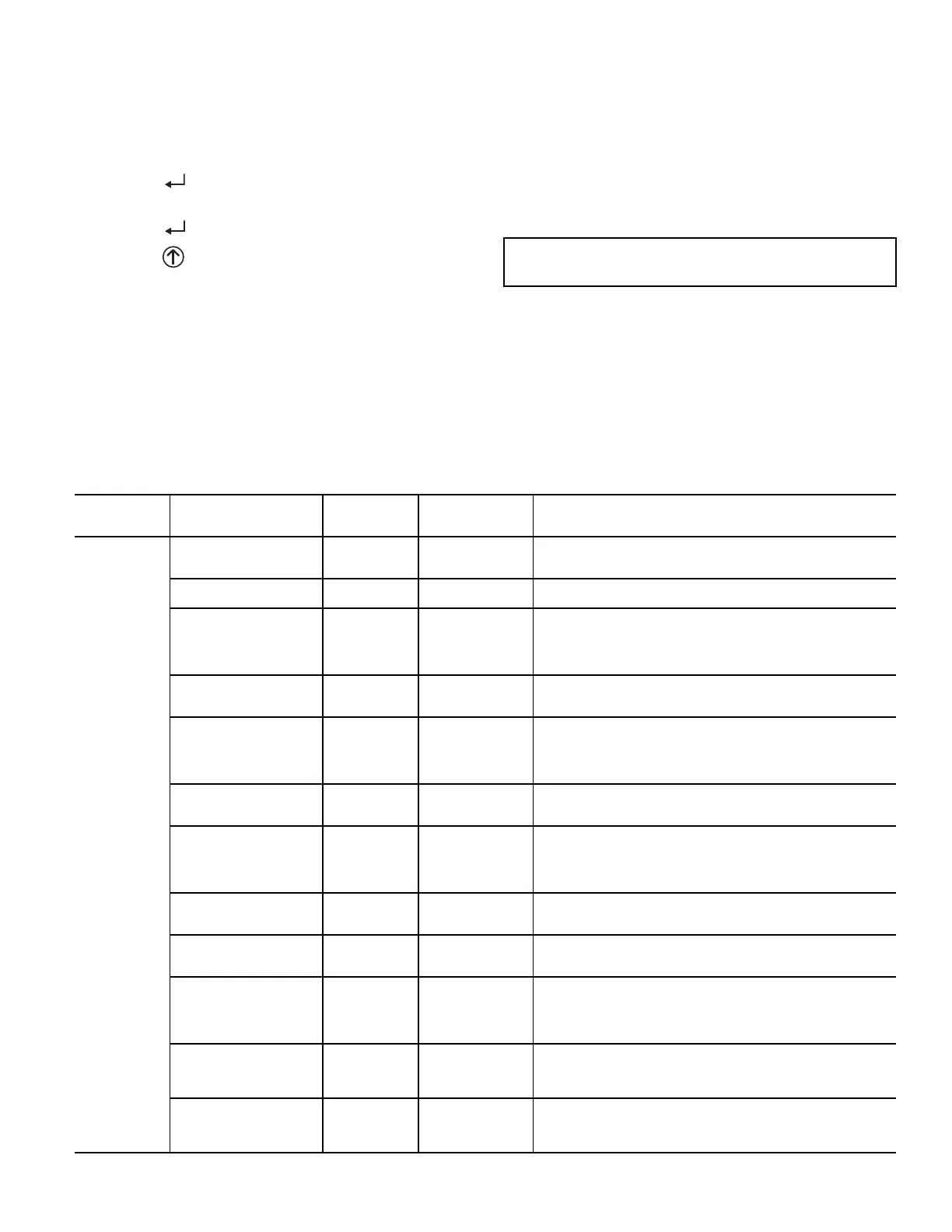
Table 27 — W7220 Menu Structure*
MENU PARAMETER
PARAMETER
DEFAULT
VALUE
PARAMETER
RANGE AND
INCREMENT
†
EXPANDED PARAMETER NAME
Notes
STATUS
ECON AVAIL NO YES/NO
FIRST STAGE COOLING DEMAND (Y1–IN)
YES = economizing available; the system can use outside air for
free cooling when required
ECONOMIZING NO YES/NO
FIRST STAGE COOLING RELAY OUTPUT
YES = outside air being used for first stage cooling
OCCUPIED NO YES/NO
OCCUPIED
YES = OCC signal received from space thermostat or unitary
controller
YES = 24 vac on terminal OCC
NO = 0 vac on terminal OCC
HEAT PUMP N/A**
COOL
HEAT
HEAT PUMP MODE
Displays COOL or HEAT when system is set to heat pump
(Non-conventional)
COOL Y1—IN OFF ON/OFF
FIRST STAGE COOLING DEMAND (Y1-IN)
Y1–I signal from space thermostat or unitary controller for cooling
stage 1.
ON = 24 vac on terminal Y1–I
OFF = 0 vac on terminal Y1–I
COOL Y1—OUT OFF ON/OFF
FIRST STAGE COOLING RELAY OUTPUT
Cool stage 1 Relay Output to stage 1 mechanical cooling
(Y1–OUT terminal)
COOL Y2—IN OFF ON/OFF
SECOND STAGE COOLING DEMAND (Y2–IN)
Y2–I signal from space thermostat or unitary controller for
second stage cooling.
ON = 24 vac on terminal Y2–I
OFF = 0 vac on terminal Y2–I
COOL Y2—OUT OFF ON/OFF
SECOND STAGE COOLING RELAY OUTPUT
Cool Stage 2 Relay Output to mechanical cooling
(Y2–OUT terminal)
MA TEMP
_ _ . _ °F
(or _ _ . _ °C)
–40°F to 150°F
(–40°C to 66°C)
SUPPLY AIR TEMPERATURE, Cooling Mode
Displays value of measured mixed air from MAT sensor.
Displays _ _ . _ F if not connected, short or out of range.
DA TEMP
_ _ . _ °F
(or _ _ . _ °C)
–40°F to 150°F
(–40°C to 66°C)
DISCHARGE AIR TEMPERATURE, after Heating section
Displays when Discharge Air Sylk Bus sensor is connected and
displays measured discharge temperature.
Displays _ _ . _F if sensor sends invalid value, if not connected,
short or out of range.
OA TEMP
_ _ . _ °F
(or _ _ . _ °C)
–40°F to 140°F
(–40°C to 60°C)
OUTSIDE AIR TEMP
Displays measured value of outdoor air temperature.
Displays _ _ . _F if sensor sends invalid value, short or out of
range.
OA HUM _ _ % 0 to 100%
OUTSIDE AIR RELATIVE HUMIDITY
Displays measured value of outdoor humidity from OA Sylk Bus
sensor.
Displays _ _% if not connected short, or out of range.

 Loading...


