66
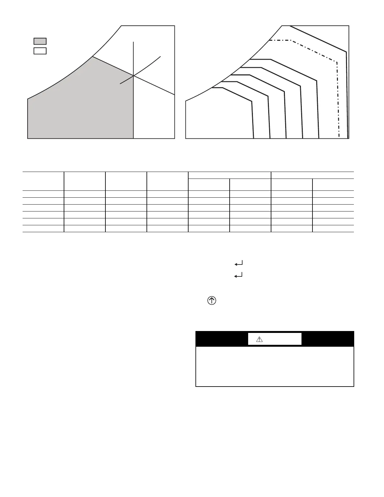
Fig. 75 — Single Enthalpy Curve Boundaries
CHECKOUT
Inspect all wiring connections at the economizer module’s termi-
nals, and verify compliance with the installation wiring diagrams.
For checkout, review the Status of each configured parameter and
perform the Checkout tests.
NOTE: For information about menu navigation and use of the
keypad, see Interface Overview on page 56.
Power Up
After the W7220 module is mounted and wired, apply power.
Initial Menu Display
On initial start up, Honeywell displays on the first line and econo-
mizer W7220 on the second line. After a brief pause, the revision
of the software appears on the first line and the second line will be
blank.
Power Loss (Outage or Brownout)
All set points and advanced settings are restored after any power
loss or interruption.
NOTE: All settings are stored in non-volatile flash memory.
Status
Use the Status menu (see Table 27) to check the parameter values
for the various devices and sensors configured.
NOTE: For information about menu navigation and use of the
keypad, see Interface Overview on page 56.
Checkout Tests
Use the Checkout menu (see page 60) to test the damper operation
and any configured outputs. Only items that are configured are
shown in the Checkout menu.
NOTE: For information about menu navigation and use of the
keypad, see Interface Overview on page 56.
To perform a Checkout test:
1. Scroll to the desired test in the Checkout menu using the
▲ and ▼ buttons.
2. Press the (Enter) button to select the item. RUN?
appears.
3. Press the (Enter) button to start the test. The unit
pauses and then displays IN PROGRESS. When the test is
complete, DONE appears.
4. When all desired parameters have been tested, press the
(Menu Up) button to end the test.
The Checkout tests can all be performed at the time of installation
or at any time during the operation of the system as a test that the
system is operable.
TROUBLESHOOTING
Alarms
The economizer module provides alarm messages that display on
the 2-line LCD.
NOTE: Upon power up, the module waits 60 minutes before
checking for alarms. This allows time for all the configured devic-
es (e.g. sensors, actuator) to become operational. The exception is
the SAT sensor which will alarm immediately.
If one or more alarms are present and there has been no keypad ac-
tivity for at least 5 minutes, the Alarms menu displays and cycles
through the active alarms.
ECONOMIZING
AVAILABLE
NOT AVAILABLE
ENTHALPY
RA HUM (%RH)
RA TEMP
TEMPERATURE
ABSOLUTE HUMIDITY
ES5
ES4
ES3
ES2 ES1
HL
P1
(T,RH)
P2 (T,RH)
SINGLE ENTHALPY
DUAL ENTHALPY
HIGH LIMIT
Table 38 — Single Enthalpy and Dual Enthalpy High Limit Curves
ENTHALPY
CURVE
TEMP. DRY
BULB (F)
TEMP.
DEWPOINT (F)
ENTHALPY
(btu/lb/da)
POINT P1 POINT P2
TEMP. (F)
HUMIDITY
(%RH)
TEMP. (F)
HUMIDITY
(%RH)
ES1 80 60 28.0 80 36.8 66.3 80.1
ES2 75 57 26.0 75 39.6 63.3 80.0
ES3 70 54 24.0 70 42.3 59.7 81.4
ES4 65 51 22.0 65 44.8 55.7 84.2
ES5 60 48 20.0 60 46.9 51.3 88.5
HL 86 66 32.4 86 38.9 72.4 80.3
CAUTION
EQUIPMENT DAMAGE HAZARD
Failure to follow this caution may result in equipment damage.
Be sure to allow enough time for compressor start-up and shut-
down between checkout tests so that you do not short-cycle the
compressors.

 Loading...


