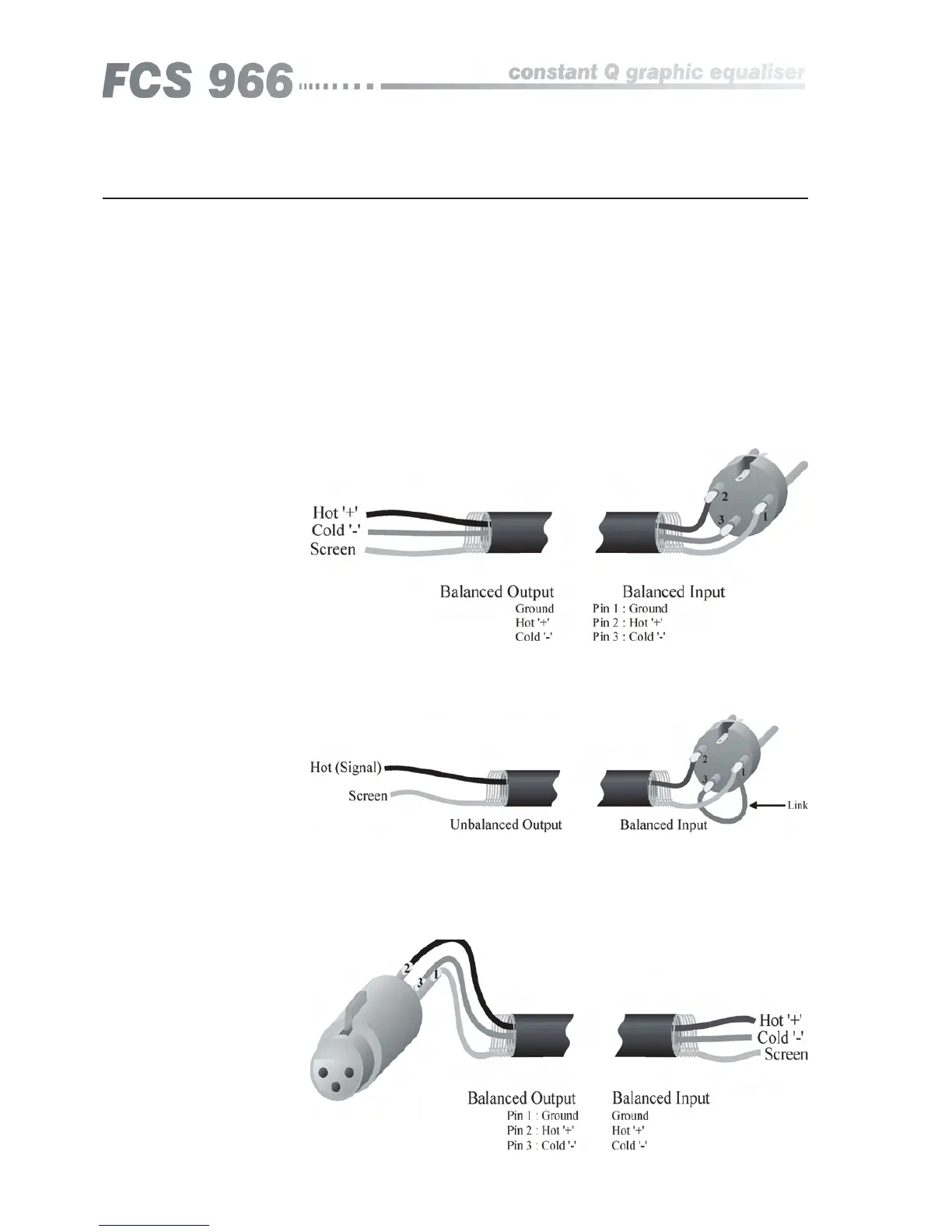
The output signals are electronically balanced and fully floating. Full
headroom is available into any load of 600 Ohms or greater. The signal ‘HOT,
+, or in phase’ signal is to pin 2, the ‘COLD, -, or out of phase’ signal is to pin
3, with pin 1 being connected directly to the chassis.
There are 2 input sockets on the rear panel of the FCS 966; Input 1 and 2. Each
is electronically balanced on standard 3 pin female XLRs at an impedance
greater than 10k Ohms. The ‘HOT, +, or in phase’ connection is to pin 2
and the ‘COLD, -, or out of phase’ connection is to pin 3. Pin 1 is internally
connected to the chassis earth via a low value capacitor. This ensures freedom
from ground loops whilst allowing good EMC performance. The screen of
the input cable should be connected to pin 1 to ensure that EMC regulations
are being met, and the cable shield ground should also be connected to the
equipment which is providing the input signal.
When feeding the FCS 966 from unbalanced sources, connect the signal
conductor to pin 2 and the cable screen to pins 1 and 3. Transformer isolated
inputs are available as a dealer fitted option.
5.0 Audio Connections
5.1 XLR Inputs
Audio Connections
Fig 5.1
Fig 5.2
Fig 5.3
5.2 XLR Outputs
966