Do you have a question about the BSS Audio FCS 966 and is the answer not in the manual?
Details compliance with European and international standards for EMC and electrical safety.
Provides essential guidelines for safe operation, including cleaning and ventilation.
Highlights critical warnings regarding grounding, rain, moisture, and internal access.
Explains cable wiring for EMC compliance and preventing ground loops.
Specifies that the mains plug or connector must remain accessible.
Instructions for unpacking the unit and checking for damage.
Details on connecting the unit to the mains power supply.
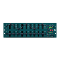
An overview of the FCS 966 graphic equalizer.
Explanation of balanced XLR input connections.
Explanation of balanced XLR output connections.
Explanation of jack input connections.
Explanation of jack output connections.
Details on the six-way pluggable terminal block connectors.
Description of the EQ bypass switch functionality.
Explanation of the gain control for level adjustment.
Details on the High Pass Filter control.
Explanation of the Low Frequency contour control.
Explanation of the High Frequency contour control.
Description of the peak reading RMS calibrated output meter.
Explanation of the overload indicators.
Details on the main graphic equalizer sliders.
Defines a graphic equalizer and its operation.
Guidance on using graphic equalizers for tonal adjustment.
Explains the concept of Constant Q in equalizers.
Guidance on using EQ to correct sound problems.
Methods for using the equalizer to reduce feedback.
Procedure for equalizing a room using pink noise and an RTA.
Applications for the High Pass Filter.
Applications for the Low Frequency contour control.
Applications for the High Frequency contour control.
Details the product warranty period and coverage limitations.
Instructions on how to report faults and return the unit for repair.
A section to record dealer and purchase details for reference.
Contact information for BSS Audio / Harman Music Group.
Technical specifications including impedance, headroom, frequency response, and noise.
Specifications for gain, filters, contours, and frequency bands.
List of potentiometers and knobs used in the FCS 966.
List of switches and input/output sockets.
List of metal parts, fuses, and screws.
Includes User Manual and Mains Lead.
Diagrams showing the unit's physical dimensions and rack mounting size.
Advice on rack mounting, vibration, heat, and magnetic radiation.
Instructions for unpacking and checking the unit's condition.
Detailed instructions for connecting the unit to AC power.
Explanation of the colour coding for the mains power lead wires.
Guidance on selecting the correct voltage and fuse for the unit.
Overview of the FCS 966 as a two-channel graphic equalizer with key features.
Explanation of the bypass function and power on/off protection.
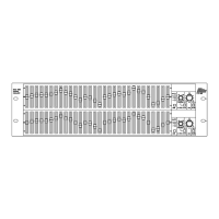
Description of available input and output connectors (XLR, Jack, Combi-Con).
Diagram illustrating the front panel controls and indicators.
Diagram illustrating the rear panel connections and features.
Explanation of bubble numbers referring to section numbers.
Overview of controls like EQ In, Gain, Filters, and Contours.
Highlights key input and output connection references.
Details on electronically balanced XLR inputs.
Explains balanced and unbalanced connection methods for XLR inputs.
Details on electronically balanced and floating XLR outputs.
Illustrates the wiring for XLR output connections.
Illustrates wiring for balanced and unbalanced jack inputs.
Specific diagram for connecting unbalanced sources via jack.
Details on jack output connections.
Illustrates wiring for balanced and unbalanced jack outputs.
Specific diagram for connecting to unbalanced outputs via jack.
Details on the six-way pluggable terminal block connectors.
Illustrates wiring for Combi-Con input and output connections.
Wiring example for connecting unbalanced output to FCS 966 input.
Wiring example for connecting FCS 966 output to unbalanced input.
Explains the function of the EQ bypass switch.
Describes output meter behavior when the unit is bypassed.
Details the gain control's range and purpose.
Discusses uses for gain control in level matching and muting.
Explains the High Pass Filter's function and applications.
Details the Low Frequency contour control and its uses.
Explains the High Frequency contour control and its applications.
Describes the peak reading RMS output meter.
Details the function of the clip indicator lights.
Explains the operation of the thirty frequency band sliders.
Defines a graphic equalizer and its role in signal processing.
Explains how graphic equalizers split the audio spectrum into bands.
Guidance on altering tonal quality and balance using EQ sliders.
Illustrates the approximate effect of sliders on different instruments.
Explains the technical term 'Q' and its implication for filter width.
Compares the filter response shapes of Constant Q and other equalizers.
Discusses the unpredictability of non-Constant Q equalizers.
Illustrates the response curve of a gyrator-type equalizer.
Illustrates the response curve of the FCS 966's Constant Q topology.
Explains why BSS chose the Constant Q topology for the FCS 966.
Step-by-step guide to using the equalizer for problem-solving.
Discusses the benefits of cutting frequencies versus boosting them.
Detailed method for reducing feedback using the equalizer.
Illustrates slider positions for feedback reduction.
Steps for equalizing room acoustics using an RTA.
Lists necessary equipment for room equalization (pink noise, RTA).
Diagram showing RTA response during room equalization.
Explains using the HP filter to manage low-frequency energy.
Discusses applications for the LF contour control.
Discusses applications for the HF contour control.
Details the product warranty period and coverage limitations.
Instructions on how to report faults and return the unit for repair.
A section to record dealer and purchase details for reference.
Contact information for BSS Audio / Harman Music Group.
Technical specifications including impedance, headroom, frequency response, and noise.
Specifications for gain, filters, contours, and frequency bands.
List of potentiometers and knobs used in the FCS 966.
List of switches and input/output sockets.
List of metal parts, fuses, and screws.
Includes User Manual and Mains Lead.
| Frequency Range | 20 Hz - 20 kHz |
|---|---|
| Power Supply | 100-240V AC, 50/60 Hz |
| Channel Separation | >80 dB |
| Maximum Input Level | +22dBu |
| Maximum Output Level | +22dBu |
| Type | Stereo Graphic Equalizer |
| Frequency Bands | 30 per channel |
| Control Range | ±12dB |
| Input Impedance | 10kΩ |
| Frequency Response | ±0.5 dB |
| THD+N | <0.01% |
| Signal to Noise Ratio | >100dB |
| EQ Range | ±12dB |
| Subsonic Filter | 18Hz, 12dB/octave |
| Input Connectors | XLR, TRS |
| Output Connectors | XLR, TRS |
| Noise | <-90dBu 20Hz-20kHz |
| THD | <0.01% |
| Dimensions | 483 x 44 x 200mm |