Introduction
2.3 INTERFACE INTRODUCTION
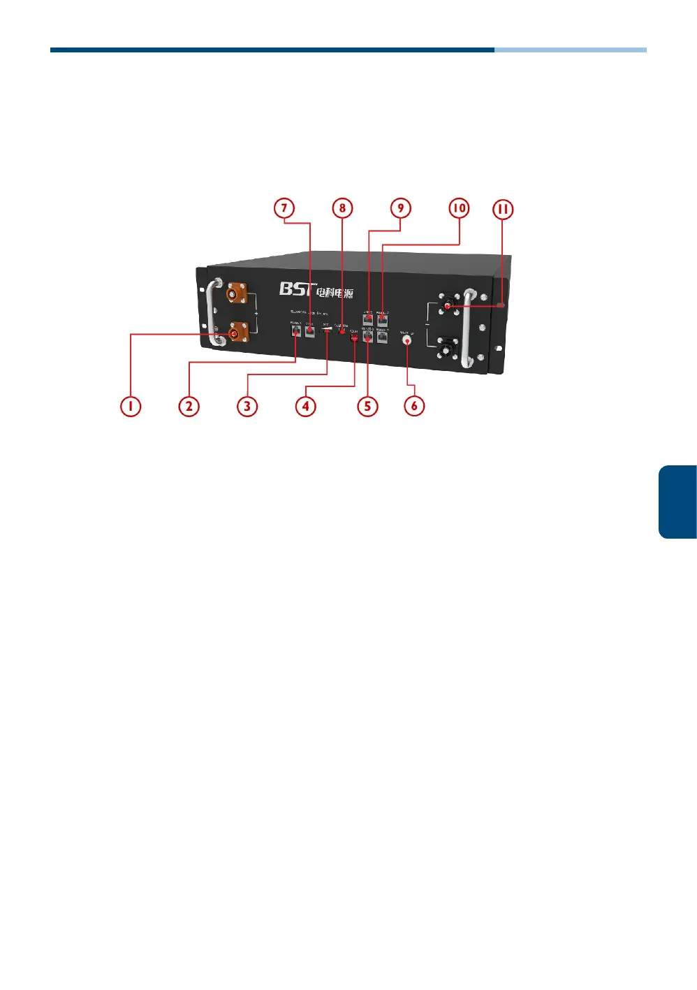
This section details the interface functions of the front panel.
Front interface:
①:Positive pole connector x 2 — For batteries parallel and power output.
②: RS485 port — For communication with inverter or EMS.
③: SOC Indicators — State of charge indicator, showing battery capacity.
④: Dial-up switch — Set the batteries as master or slaves in parallel model.
⑤: RS485-3 port — For communication with Growatt inverters.
⑥: ON/OFF button — To start or shut down the battery.
⑦: CAN-1 port — For communication with BST, Sofar, Sermatec, Goodwe, Solis and
Deye inverters.
⑧: Status Indicators — Includes RUN and ALARM indicator.
⑨: CAN2- port — For communication with Victron and SMA inverters.
⑩: RS485-2 port — For inner communication between parallels batteries and
communication with Voltronic inverters.
⑪: Negative pole connector x 2 — For batteries parallel and power output.
04



 To Next Page