Do you have a question about the BST ekrPro Com60 and is the answer not in the manual?
Provides an overview of the operating manual's purpose, system components, and controller utilization.
Details technical specifications of the controller and associated sensors, including power, dimensions, and interfaces.
Outlines essential guidelines for the safe transport and proper storage of the equipment.
Describes the necessary procedures for safely decommissioning and disposing of the system.
Covers physical installation requirements, site preparation, mounting dimensions, and electrical cabling.
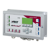
Explains the controller's graphics display, keypad layout, navigation, and function keys.
Details the system setup procedures, including unit addressing, CAN bus configuration, and password management.
Provides board overviews, detailed terminal diagrams, and service indicator LED explanations.
Explains the controller's graphics display, keypad functions, system navigation, and button operations.
Covers general operation, graphics display usage, changing settings, and starting scanning modes.
Details how to acknowledge errors, self-deleting errors, and lists common fault causes and solutions.
Provides guidance on maintaining the controller, sensors, and actuators, including cleaning and safety.
Outlines the procedure to access and navigate the system's comprehensive setup menu structure.
Lists all factory default parameter values for system configuration and reset.
Offers practical step-by-step examples for initial startup of actuators and sensor positioning devices.
Presents detailed diagrams for terminal assignments, board overview, and plug connector pinouts.
Illustrates the overall system architecture and interconnections of BST Bus System components.
Details the specific flange connection plate layout for the XT version of the controller.
| Brand | BST |
|---|---|
| Model | ekrPro Com60 |
| Category | Computer Hardware |
| Language | English |