Terminal diagrams / Service displays B 4
ekrPro Com
60
web guide controller
EDV-No.: MD.191.01.05/1.6.x Appendix B 4
with analog sensors Date: 23.11.2007 Page: 3/9
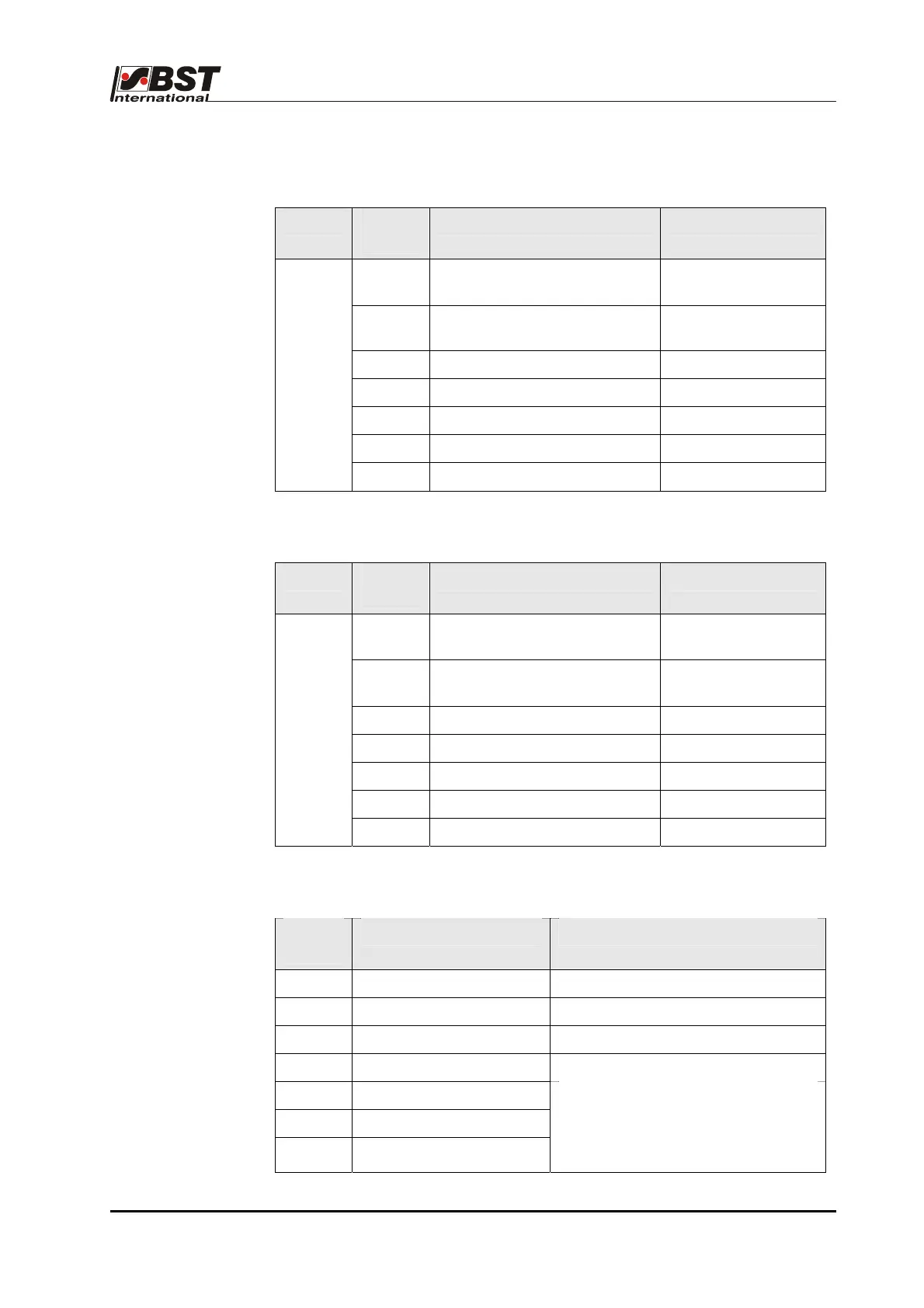
B 4.2.2 Terminal strip X1; Sensor 1:
Plug Terminal
X1
Function Remarks
1 Internal connection
to terminal 8
2 IR pulse + 5 V/
Synchronisation for US sensor
3 IR pulse GND
4 + 12 V Output + 12 V
5 GND
6 - 12 V Output – 12 V
X50
7 Analog input 4
B 4.2.3 Terminal strip X2; sensor 2:
Plug Terminal
X2
Function Remarks
8 Internal connection
to terminal 1
9 IR pulse +5V/
Synchronisation for US sensor
10 IR pulse GND
11 +12V Output ±12V
12 GND
13 -12V Output -12V
X51
14 Analog input 6
B 4.2.4 Terminal strip X3; Position controller (SC) / servo-center component OMG 4 / Namur:
Terminal
X3
Function Remarks
44 +12V Output ±12V
45 GND
46 -12V Output -12V
47 Analog input 3
48 Namur Out
49 Namur A
50 Namur B
A link must be fitted across
terminals 47 and 48 if you are
using a Namur encoder connected
to terminals 49 and 50.