Operation C 2
ekrPro Com
60
web guide controller EDV-No.: MD.191.01.05/1.6.x Chapter: C 2
with analog sensors Date: 23.11.2007 Page: 13/19
C 2.4.4 Manual material set-up
for sensors T 62 D 1 and TW 54 C5
C 2.4.4.1 Settings for the T 62 D1
Prior to carrying out of the material setup, the zero point should be
reset for sensor T62 D1. This is different dependent on whether
the sensor is being used for line sampling or for contrast sampling.
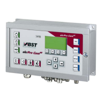
a) Line scanning (lines of 0,5 … 5 mm)
Place the switch on the housing in “Linie” position and focus the
light spot on the primary colour of the material (that is outside of
the line), then set the “Nullpunktabgleich” (zero alignment)
potentiometer for both luminous diodes to be extinguished.
We recommend that the zero point compensation is carried out
with inclined sensor (the tilt position must be determined
empirically) when both LED´s illuminate as a result of intensive
surface reflections (e.g. metal foils).
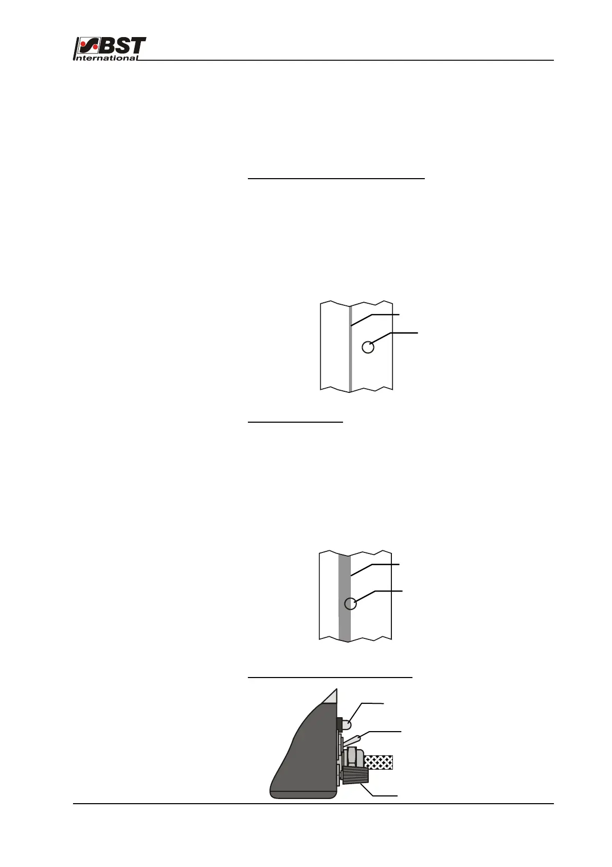
b) Contrast scanning
The switch on the casing to be switched to “Kante” (edge) mode.
Set the sensor in a manner for ensuring that the contrast to be
scanned is in the centre of the light spot. Then extinguish both
luminous diodes by employing the “Nullpunktabgleich” (zero
alignment) potentiometer on the sensor. We recommend that the
zero point compensation is carried out with inclined sensor (the tilt
position must be determined empirically) when both LED´s
illuminate as a result of intensive surface reflections (e.g. metal
foils).
Adjustment elements on the T62 D1
Light spot
Line
Contrast
Light spot
Zero alignment
LEDs
Changeover switch
contrast/line