Description A 1
ekrPro Com
60
web guide controller
EDV No.: MD.191.01.05/1.6.x Chapter: A 1
with analog sensors Date: 23.11.2007 Page: 2/5
A 1.4 General
Settings
A 1.4.1 Assignment of sensors to the
to the scanning mode selection keys
In this operating manual, the edge sensors that are connected to
the controller are designated with “sensor 1” and “sensor 2”. On
the operating keyboard of the controller, the guiding mode
selection keys have the lettering „SENSOR LEFT“ and „SENSOR
RIGHT“ respectively.
According to the BST definition, the following link applies:
SENSOR LEFT = Sensor 1
SENSOR RIGHT = Sensor 2
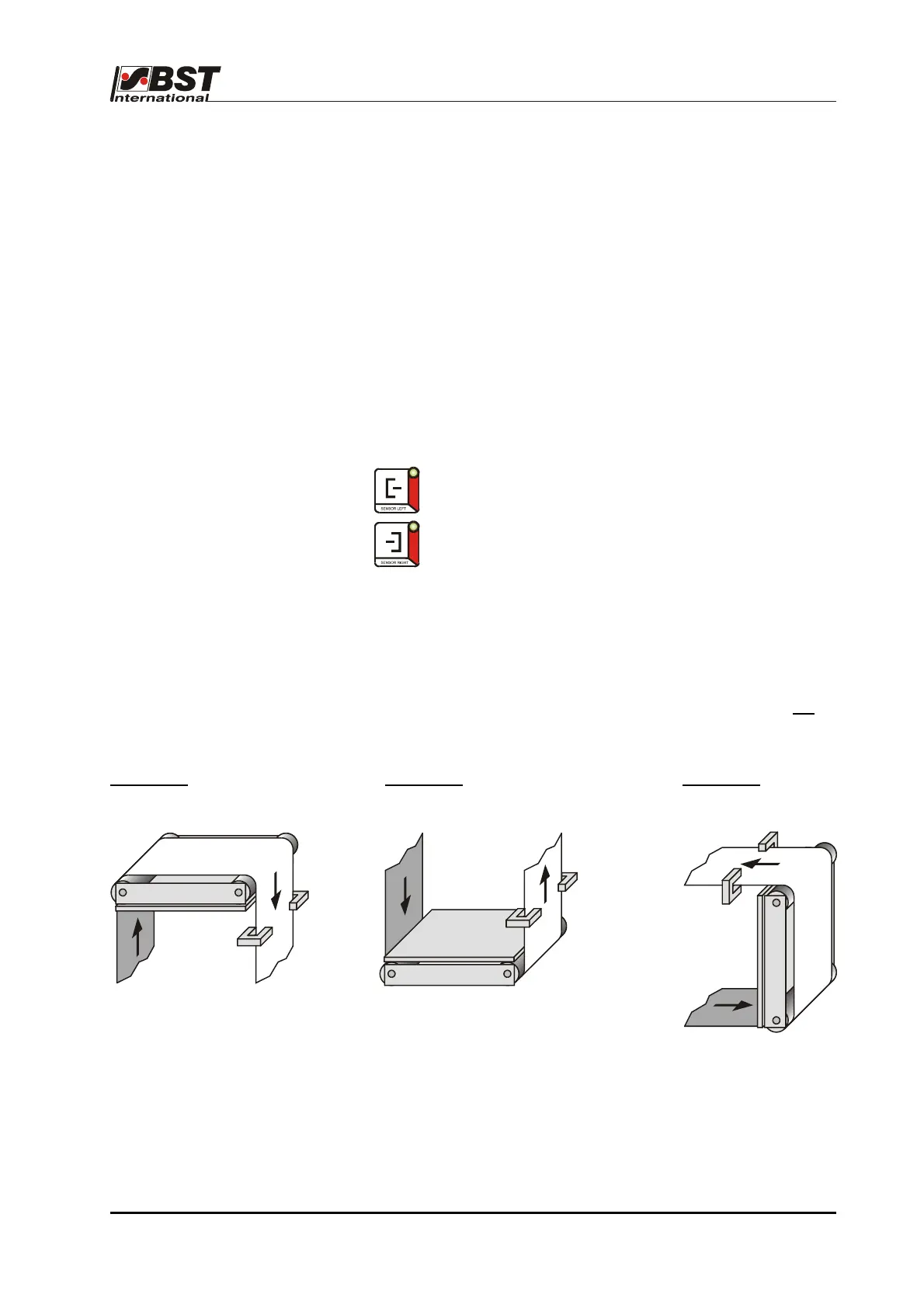
The following is valid in respect of the sensor mounting positions:
The sensor, which is located to the left of the material in the
web movement direction (when looking from the material top
side), is sensor 1.
The material top side is the side of the material web which is not
in
direct contact with the deflection pulleys of the pivoting frame.
Example 1:
Example 2: Example 3:
As standard, sensor 1 (Sensor left) must be connected to
connector X50 (terminal X1), while sensor 2 (Sensor right) must be
connected to connector X51 (terminal X2) of the terminal board.
Sensor left
(Sensor 1)
Sensor right
(Sensor 2)
Sensor right
(Sensor 2)
Sensor left
(Sensor 1)
Sensor left
(Sensor 1)
Sensor right
(Sensor 2)