Terminal diagrams / Service displays B 4
ekrPro Com
60
web guide controller
EDV-No.: MD.191.01.05/1.6.x Appendix B 4
with analog sensors Date: 23.11.2007 Page: 9/9
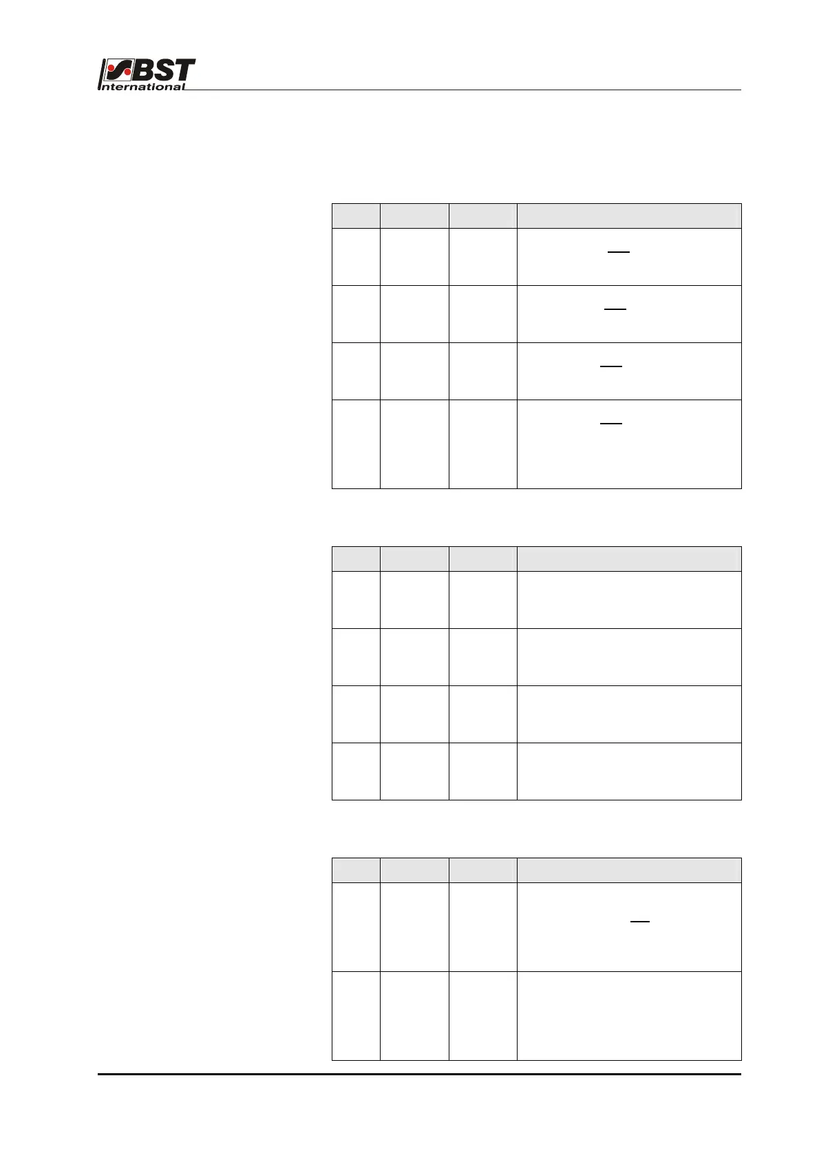
B 4.3 Service indicator displays
B 4.3.1 LEDs “Power supply“
LED Name Status Significance
H20 +12V OFF
ON
Internal +12V not present
Internal +12V present
H21 -12V OFF
ON
Internal -12V not present
Internal -12V present
H22 +5V OFF
ON
Internal +5V not present
Internal +5V present
H24 +5PV OFF
ON
Internal +5V not present (lamp
voltage)
Internal +5V present (lamp
voltage)
B 4.3.2 LEDs “Digital outputs“
LED Name Status Significance
H64 OFF
ON
Digital output 0 OFF
Digital output 0 ON
H65 OFF
ON
Digital output 1 OFF
Digital output 1 ON
H66 OFF
ON
Digital output 2 OFF
Digital output 2 ON
H67
OFF
ON
Digital output 3 OFF
Digital output 3 ON
B 4.3.3 LEDs “FVG stop switches“
LED Name Status Significance
H59 OFF
ON
Reference switch 1 (FVG)
Outer limit switch not activated
Reference switch 1 (FVG)
Outer limit switch activated
H62 OFF
ON
Reference switch 2 (FVG)
Inner limit switch not activated
Reference switch 2 (FVG)
Inner limit switch activated