Commissioning B 3
ekrPro Com
60
web guide controller EDV No.: MD.191.01.05/1.6.x Chapter: B 3
with analog sensors Date: 23.11.2007 Page: 43/73
B 3.7.5.5.4 FVG Pro
The FVG Pro submenu is used when the FVG 2MK Op. mode has
been selected (usually when using an FVG 2MK). In this case, each
FVG needs to be adjusted separately. The terms used here FVG 1
(Slide 1) and FVG 2 (Slide 2) relate to the arrangements in
accordance with Point A 1.4.5.
The safety features are identical for both FVGs. The procedure for
FVG 1 (Slide 1) is used as the example here:
Homing Direction –
Retraction direction and limit switch assignment
The retraction direction of the sensors and the assignment of the
limit switches are set up in the next steps.
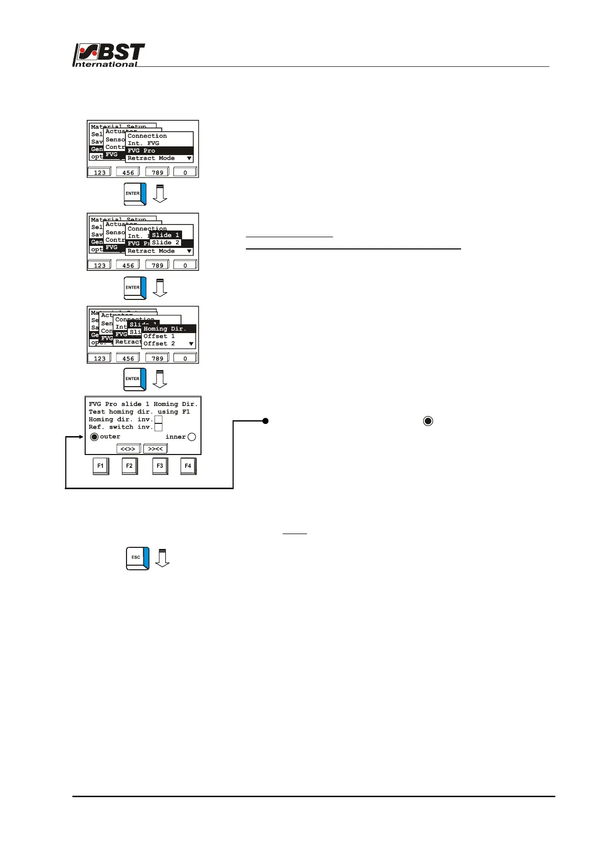
1. Mark FVG Pro in the FVG selection window and then
confirm by pressing ENTER. Select Slide 1 and confirm by
pressing ENTER.
2. Select Homing Dir. from the sub-directory and then press
ENTER to open the inputting menu.
3. Press the F1 key to check the selected retraction direction.
By pressing the F1 key, the FVG slide must move outwards
(into the homing position).
After the homing position is reached, the limit switch with the
outer label must be activated ( ).
Exit the window without making any changes if homing
direction and limit switch assignment are correct.
If the FVG slide moves inwards when the F1 key is pressed,
then the checkbox Homing dir. inv. should be activated.
If the limit switch with label inner is activated in the homing
position, then the checkbox Ref. switch inv. should be
activated.
Note:
If the limit switch is activated but no checkbox
(outer or inner) is activated, then the limit switch
requires testing.
4. Press the ESC button to exit the inputting menu after you
have entered the setting.