Installation B 1
ekrPro Com
60
web guide controller EDV No.: MD.191.01.05/1.6.x Chapter: B 1
with analog sensors Date: 23.11.2007 Page: 6/7
B 1.5.2 Installation
line sensor T 62 D 1
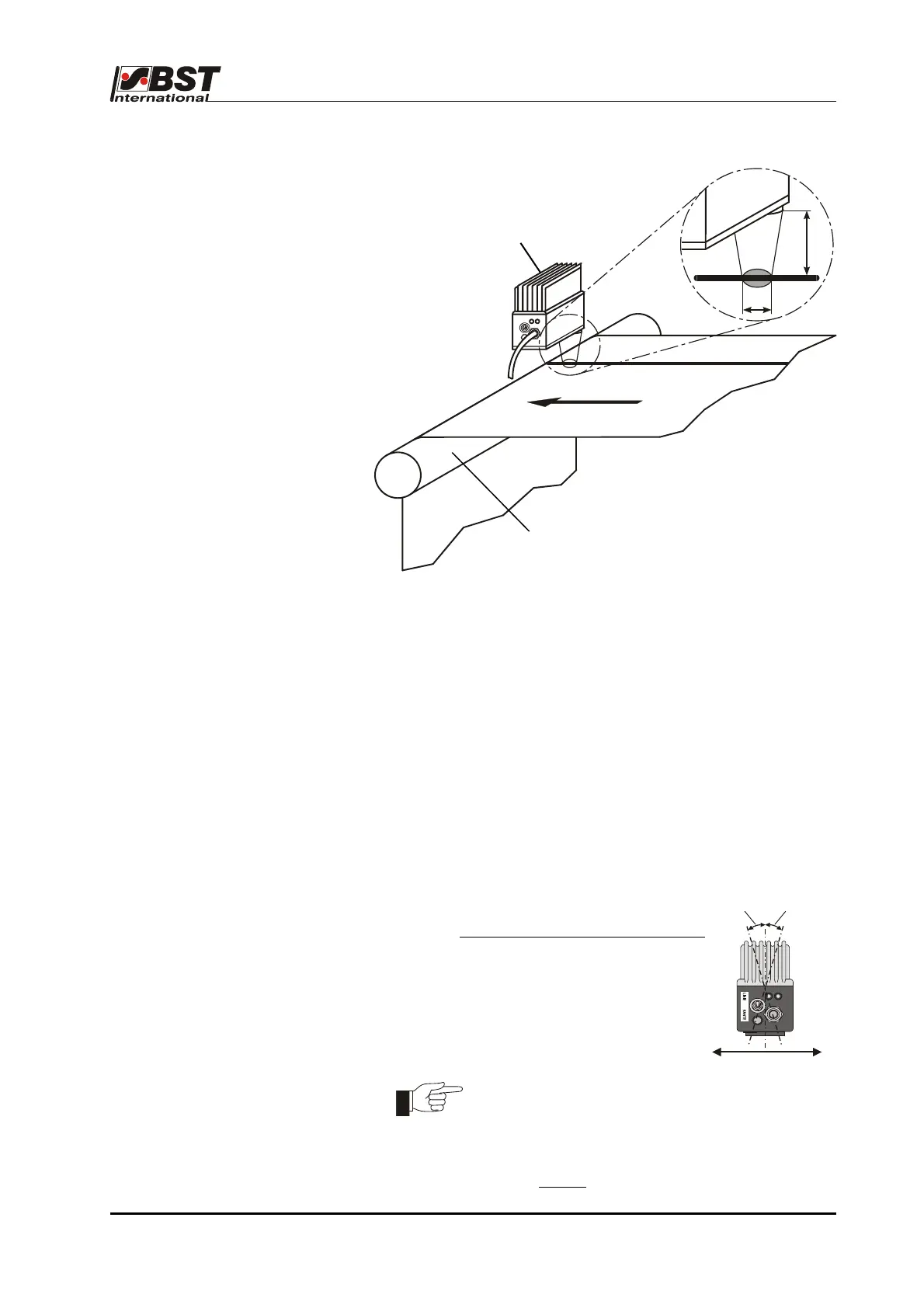
Scanning arrangement T 62 D 1
The following points must be adhered to during installation of the
T 62 D 1 in order to realise optimum guiding results:
• The line sensor should be mounted on a torsionally rigid base.
• The line / contrast must be placed at right angles to the
longitudinal axis of the sensor (see drawing).
• The scanning should be carried out on a deflection roller.
This will ensure that any material web height fluctuations are
eliminated at the scanning point.
• The distance between the sensor scanning optics and the
material web must be set so that there is a light spot with a
diameter of approximately 8 mm (corresponding to a scanning
distance of approximately 17 mm) on the web.
• We recommend that the sensor angle is
reduced by 5° - 15° in the web running
direction when using very reflective materials
.
The light spot diameter can be reduced in size by
altering the distance from the web in order to
optimise the system when working with poor
contrast or narrow lines.
The scanning distance clearance must never
exceed 30 mm
.
T 62 D 1
Deflection roller
ø8
17
5
…15
5
…15
Web running direction