Commissioning B 3
ekrPro Com
60
web guide controller EDV No.: MD.191.01.05/1.6.x Chapter: B 3
with analog sensors Date: 23.11.2007 Page: 11/73
B 3.5.3 Setting the actuator
guiding direction
For standard systems, the EMS17 is registered as the actuator.
The direction has to be set for it.
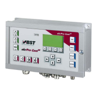
1. Select the sub-directory Direction from the menu Actuator.
Confirm the selection by pressing ENTER.
If necessary, the actuator guiding direction for manual mode
can be reversed by activating the checkbox Mot. Dir. Inverted.
The rotational direction can be checked on the spot.
Drive the actuator using the F2 or F3 key.
If key F2 is pressed, the actuator must move the material web
in the direction of sensor 1, if F3 is pressed it must move it
towards sensor 2!
Pressing F2 or F3 automatically changes the controller to
“manual” operating mode.
The sensor allocation can be checked on the spot. Press the
MENU button. The operating display is shown.
Cover one sensor. The change to the coverage range shows
the allocation.
After this, press the MENU key to ENTER to the settings
menu.
2. Press the ESC button to exit the window.
B 3.5.4 Setting the actuator
path limits
From here it is possible to limit the adjustment travel of the
actuator.
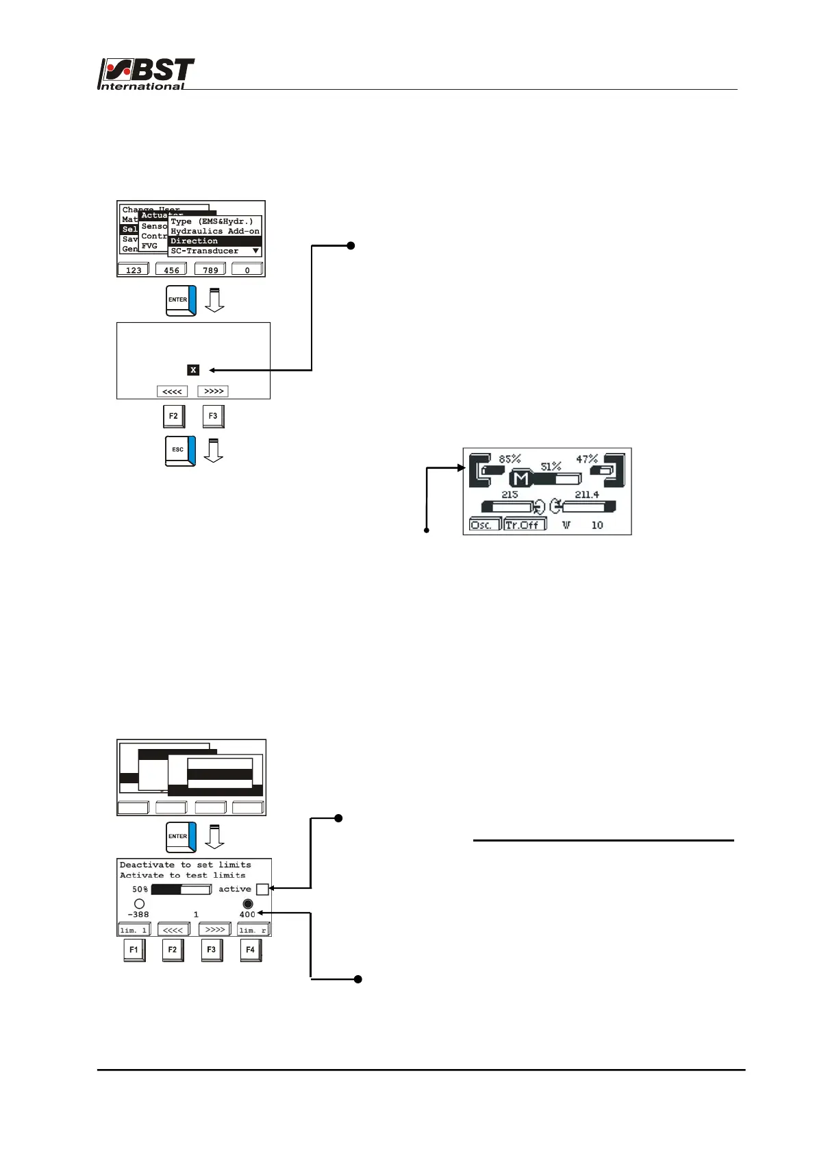
1. Select Actuator in General Setup, then the sub-directory
SC-Component and finally Pos. Limit.
Confirm the respective selection by pressing ENTER.
2. Use the vertical arrow keys to deactivate the checkbox active.
This deactivates the function of both limit switches.
The settings can only be entered in the deactivated state.
3. Use the F2 key to drive the actuator until it reaches the
required left limit switch position.
The actual position of the actuator supplied by the position
feedback is shown in the middle above the F2 and F3 keys.
4. Confirm this position by pressing the F1 key.
The limit switch position is stored.
The corresponding position value is shown below the
checkbox.
123 456 789 0
Change User
Material Setup
Sel. Std. System
opt. Logic
General Setup
Actuator
Sensors/EFE
Control Loop
FVG
Type (EMS&Hydr.)
Hydraulics Add-on
Directions
SC-Transducer
Type & Dir.
SC W & XP
Pos. Limit
Toggle Man Dir. until
F2 moves to sensor 1
Mot. Dir. Inverted