Commissioning B 3
ekrPro Com
60
web guide controller EDV No.: MD.191.01.05/1.6.x Chapter: B 3
with analog sensors Date: 23.11.2007 Page: 65/73
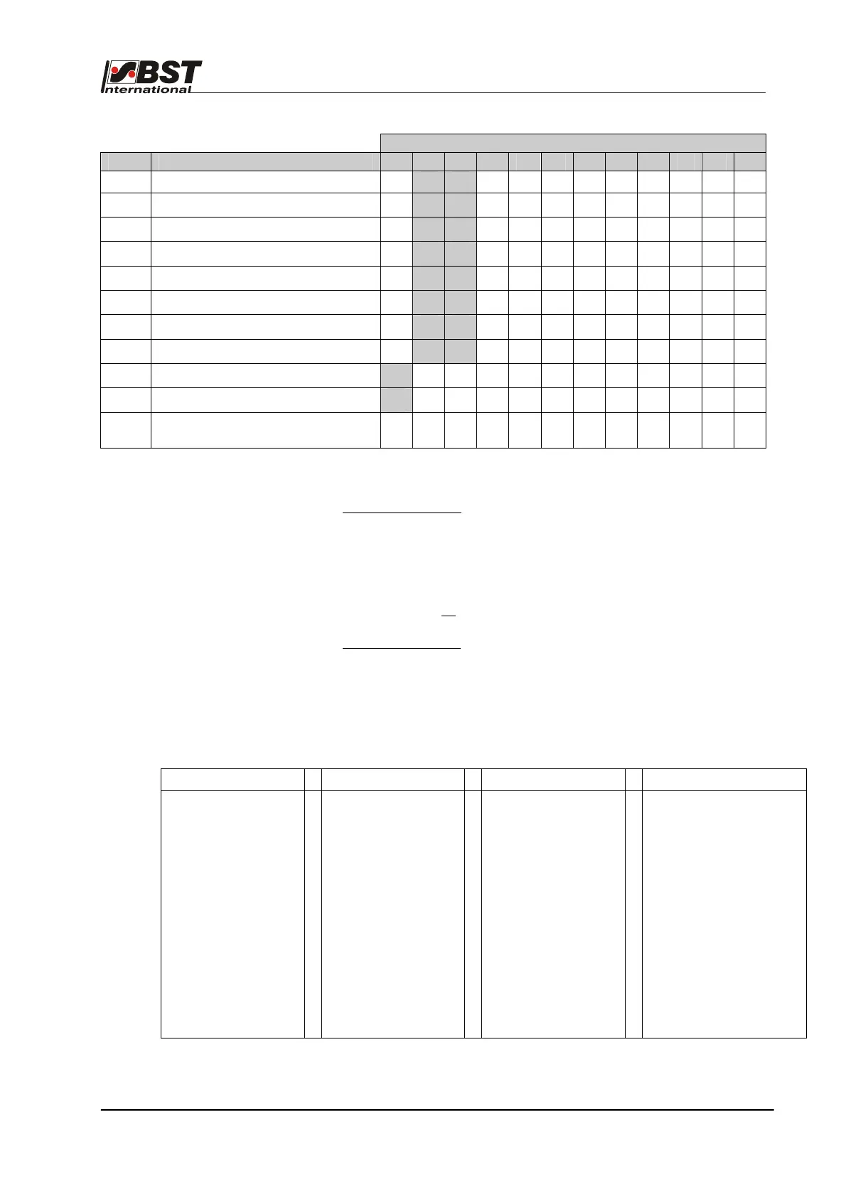
Terminal
Line Signification 85 84 83 82 81 80 79 78 77 76 75 74
20 Set limit switch 1 X
1 0
X X X X X X X X X
21 Reset Lim.Sw. 1
X
0 0
X X X X X X X X X
22
Reset Lim.Sw. 1
X
1 1
X X X X X X X X X
23 Set Lim.Sw. 2
X
0 1
X X X X X X X X X
24
Reset Lim.Sw. 2
X
0 0
X X X X X X X X X
25
Reset Lim.Sw. 2
X
1 1
X X X X X X X X X
26
Set Overtemp.
X
1 1
X X X X X X X X X
27
Reset Overtemp.
X
0 0
X X X X X X X X X
28
Ext. Unlock
1
X X X X X X X X X X X
29
Ext. lock
0
X X X X X X X X X X X
30 -
60
Do Nothing
(reserved)
1 1 1 1 1 1 1 1 1 1 1 1
0 = 0 V signal 1 = 24 V signal X = not relevant
Controller interlock
The controller interlock is generally activated. The function can only
be deactivated by application of a "1” signal (24 V=) to terminal 53.
If the controller block is activated, the output of the output stage is
switched off.
The actuator will not carry out any guiding movements.
This is valid for all
operating or guiding modes (AUTO, MAN, SC).
Keyboard interlock
All of the controller’s keys are locked by a “1“ (24 VDC) on
terminal 85. The controller can be controlled via the keyboard when
this signal is no longer set.
The individual lines in the truth table can each be allocated the
following meaning:
Significance
Significance
Significance Significance
• Do Nothing
• set AUTO
• set MAN
• set SC
• opmode clear
• set Edge 1
• set Edge 2
• set Center 1&2
• set Edge 3
• set Edge 3 inv.
• guid. mode clear
• Motor Left
• Motor Right
• Motor Stop
• FVG Left
• FVG Right
• FVG Stop
• Set Lim.sw. 1
• Reset Lim.sw. 1
• Set Lim.sw. 2
• Reset lim.sw. 2
• Set Overtemp.
• Reset Overtemp.
• Keyb. Lock ON
• Keyb. Lock OFF
• Osc. ON
• Osc. OFF
• Tear Out ON
• Tear Out OFF
• ext. Lock
• ext. Unlock
• Set W.
• Set Prepos. E1
• Reset Prepos. E1
• Set Prepos. E2
• Reset Prepos. E2
• Set Prepos. C1&2
• Reset Prepos. C1&2
• Set Prepos. Center
• Reset Prepos.
Center
• Copy cur.pos. to
Prepos.