Terminal diagrams / Service displays B 4
ekrPro Com
60
web guide controller
EDV-No.: MD.191.01.05/1.6.x Appendix B 4
with analog sensors Date: 23.11.2007 Page: 8/9
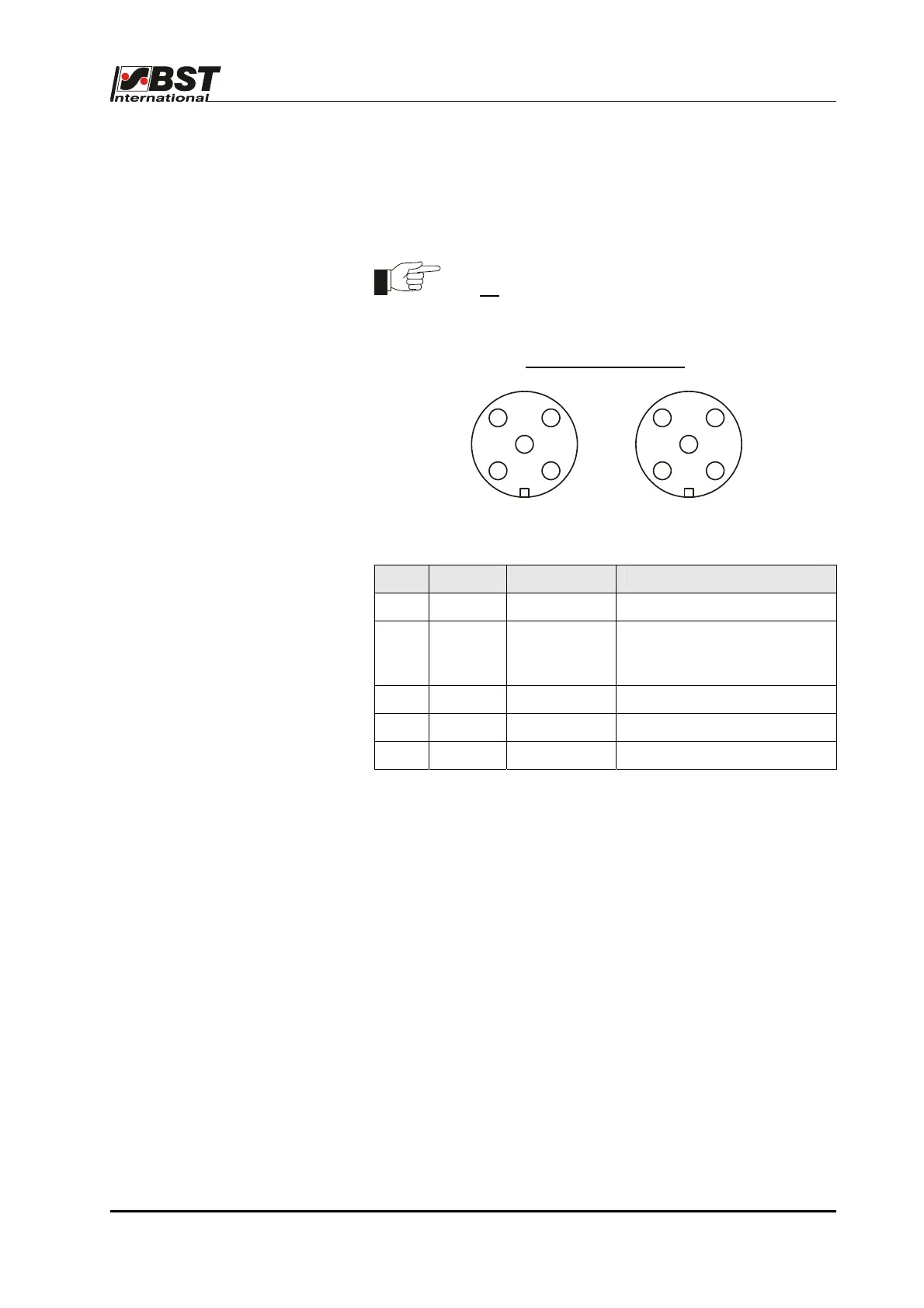
B 4.2.15 CAN connection assignments:
The controller is connected to the CAN bus via a 5-pin M12 micro
style connector.
The maximum individual contact nominal current
is 4A
.
Contact assignments in the plug connector:
View on the screw side
Pin Colour Signal Significance
1 CAN_SHLD Shield
2 Directly connected to pin 2
of the second CAN-plug
connector
3 CAN_GND
4 CAN_H Bus line (dominant high)
5 CAN_L Bus line (dominant low)
1
2
3
4
5
Socket
(female)
21
4
3
5
Plug
(male)