Installation B 1
ekrPro Com
60
web guide controller EDV No.: MD.191.01.05/1.6.x Chapter: B 1
with analog sensors Date: 23.11.2007 Page: 7/7
B 1.5.3 Installation
reflection sensor TW 54 C 5
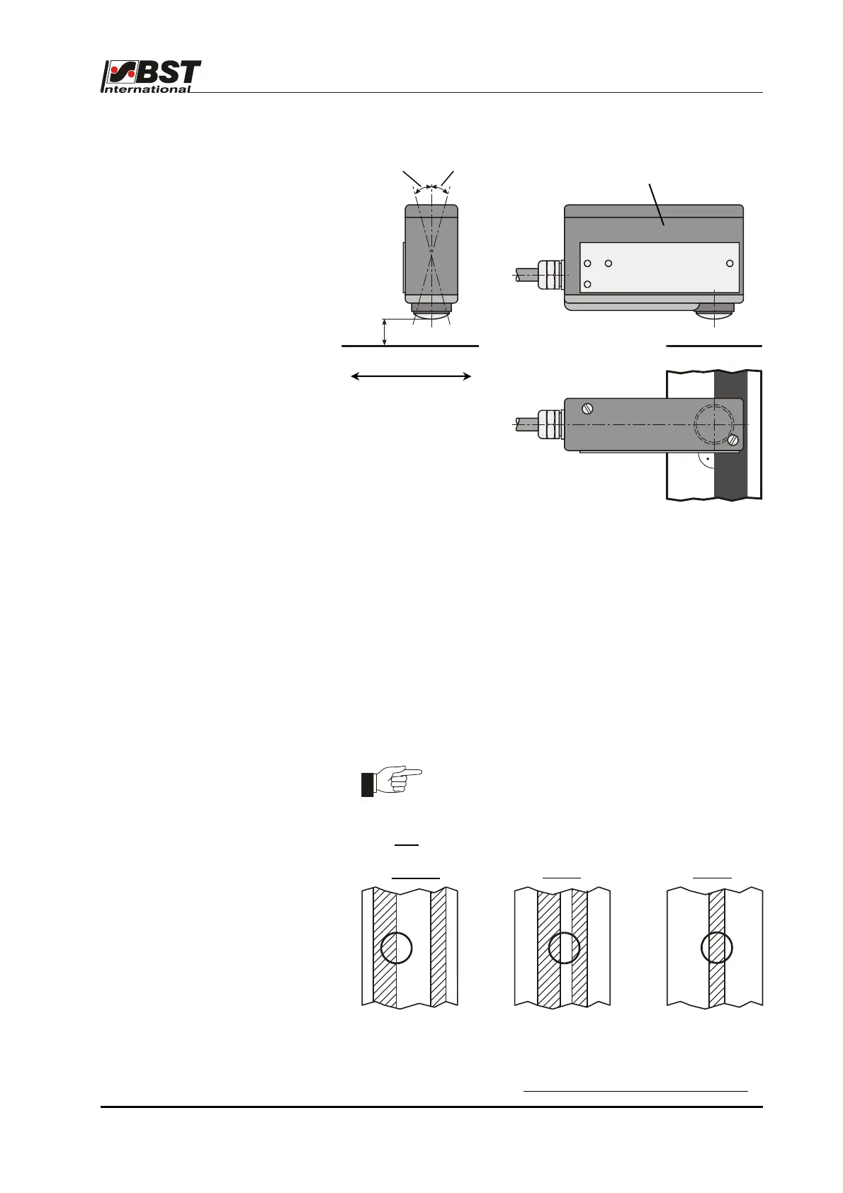
You must abide by the following points when installing the
TW 54 C 5 reflection scanner in order to realise optimum guiding
results:
• The line sensor should be mounted on a torsionally rigid base.
• The line / contrast must be placed at right angles to the
longitudinal axis of the sensor (see drawing).
• The scanning should be carried out on a deflection roller.
This will ensure that any material web height fluctuations are
eliminated at the scanning point.
• The distance between the sensor scanning optics and the
material web has to be 6 - 12 mm, depending on the required
measuring range (diameter of the light spot).
The measuring range (light spot diameter)
depends on the distance between the contrast
transitions.
Only one
contrast transition may be located within the light spot.
correct
wrong wrong
Distance scanning optics D material web: 6 - 12 mm
Light spot diameter: 7.5 – 4 mm
• We recommend that the sensor angle is reduced by 5° - 15° in
the web running direction when using very reflective materials
.
6…12
TW 54 C 5
5°…15°
web running direction
5°…15°