Terminal diagrams / Service displays B 4
ekrPro Com
60
web guide controller
EDV-No.: MD.191.01.05/1.6.x Appendix B 4
with analog sensors Date: 23.11.2007 Page: 5/9
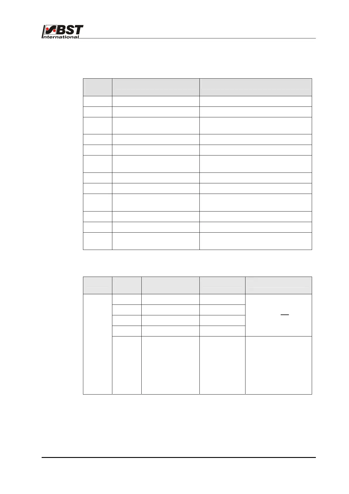
B 4.2.9 Terminal strip X10; Enable and reference switch (FVG):
Terminal
X10
Function Remarks
51 GND GND for enable actuator
52 +24V +24V output for enable actuator
53 Enable actuator Enable actuator input. Link to terminal 52
if not used
54 GND GND for enable FVG
55 +24V +24V output for enable FVG
56 Enable FVG Enable FVG input. Link to terminal 55 if
not used
57 GND GND for reference switch 1
58 +24V +24V output for reference switch 1
59 Reference switch 1 (FVG)
outer stop switch
Reference switch 1 input (FVG)
60 GND GND for reference switch 2
61 +24V +24V output for reference switch 1
62 Reference switch 2 (FVG)
inner stop switch
Reference switch 2 input (FVG)
B 04.02.10 Terminal strip X12; FVG stepping motor:
Plug Terminal
X12
Motor plug pin
assignments
Function Remarks
36 3 Winding 2A
37 4 Winding 2B
38 1 Winding 1A
39 6 Winding 1B
Outputs are not
short
circuit protected
X65
Shield Shield The shield is not
attached. The end of
the line must be
correctly stripped back
and insulated by using
sleeves against short
circuits caused by the
screen.
Attention! The stepping motor output stages are not
protected against short circuits. Short circuits or
wrong wiring (reversed polarity) can destroy the
FVG!