Commissioning B 3
ekrPro Com
60
web guide controller EDV No.: MD.191.01.05/1.6.x Chapter: B 3
with analog sensors Date: 23.11.2007 Page: 61/73
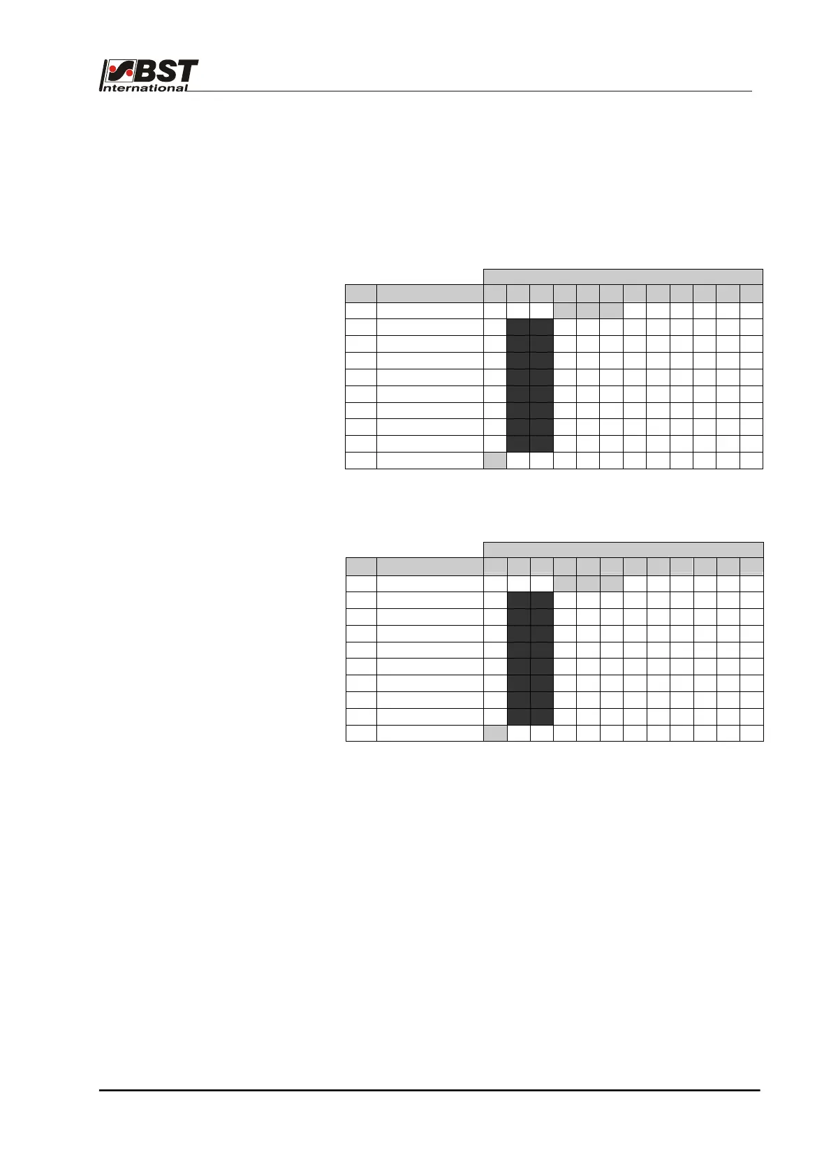
Example 2: The function Tear-off detection is to be assigned to
the digital inputs (lines 21 and 22).
The following section of the truth table shows that lines 21 and 22
belong to a bit-block with a total of 8 lines (lines 21 to 28).
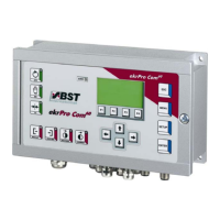
Factory allocation of functions
with the corresponding standard bit-patterns
Terminal
Line
Significance
85 84 83 82 81 80 79 78 77 76 75 74
20 FVG stop X X X 1 1 1 X X X X X X
21 Set Lim.Sw. 1 X
1 0
X X X X X X X X X
22 Reset Lim.Sw. 1 X
0 0
X X X X X X X X X
23 Reset Lim.Sw. 1 X
1 1
X X X X X X X X X
24 Set Lim.Sw. 2 X
0 1
X X X X X X X X X
25 Reset Lim.Sw. 2 X
0 0
X X X X X X X X X
26 Reset Lim.Sw. 2 X
1 1
X X X X X X X X X
27 Set Overtemp. X
1 1
X X X X X X X X X
28 Reset Overtemp. X
0 0
X X X X X X X X X
29 Keyb.Lock ON 1 X X X X X X X X X X X
User defined allocations -
function Tear-off detection on lines 21 and 22
Terminal
Line
Significance
85 84 83 82 81 80 79 78 77 76 75 74
20 dig. Left/Right Stop X X X 1 1 1 X X X X X X
21
Tear Out ON
X
1 X
X X X X X X X X X
22
Tear Out OFF
X
0 X
X X X X X X X X X
23 Do Nothing 1
1 1
1 1 1 1 1 1 1 1 1
24 Do Nothing 1
1 1
1 1 1 1 1 1 1 1 1
25 Do Nothing 1
1 1
1 1 1 1 1 1 1 1 1
26 Do Nothing 1
1 1
1 1 1 1 1 1 1 1 1
27 Do Nothing 1
1 1
1 1 1 1 1 1 1 1 1
28 Do Nothing 1
1 1
1 1 1 1 1 1 1 1 1
29 Keyb.Lock ON 1 X X X X X X X X X X X
The procedure for changing the allocations can be divided into three
steps, which are described on the following page.