Commissioning B 3
ekrPro Com
60
web guide controller EDV No.: MD.191.01.05/1.6.x Chapter: B 3
with analog sensors Date: 23.11.2007 Page: 20/73
Criteria for detecting a tear:
To detect a tear, at least one of the two following criteria must be
fulfilled:
1. Exceeding / undershooting of the preset threshold value
If the sensor signal exceeds or falls below the set threshold value
(threshold), then this is recognised as a tear.
After a preset delay time (delay) has elapsed, the web guiding
system is automatically blocked.
Blocking of the guidance system is lifted, as soon as the sensor
signal again lies above/below the set threshold value and the set
run-on time (hold time) has elapsed.
2. Exceeding of the preset maximum rate of change of the sensor
signal.
The system continuously checks the rate of change speed of the
sensor signal in both positive and negative directions. If the
preset maximum permissible rate of change (sig. chg. lim.) is
exceeded, then this is recognized as a tear.
After a preset delay time (delay) has elapsed, the web guiding
system is automatically blocked.
If the set rate of change is undershot, then blocking of the guiding
system is not
lifted.
Lifting of the blocking is only implemented if the preset threshold
value (threshold) is again undershot (see point 1).
Conditions for guiding on interrupted printed or contrast edges
For trouble-free operation of the control unit, the following conditions
must be fulfilled:
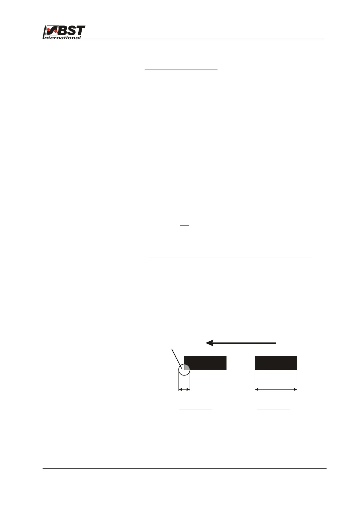
1. Minimum mark length
The printed or contrast edge to be sampled must not fall below
the minimum mark length L
min
. The minimum mark length
depends on the maximum web speed, v
max
, the sampling cycle, t,
and the diameter, d, of the light spot of the contrast sensor used.
It can be calculated using the following formula.
L
min
[m] = * 3 * t [s] +
L
min
= minimum mark length [m]
v
max
= max. web speed [m/min]
t = sampling cycle [s] = 0.004 s
d = light spot diameter [mm]
V
max
[m/min]
60 s/min
d [mm]
1000 mm/m
dL
Light spot