Commissioning B 3
ekrPro Com
60
web guide controller EDV No.: MD.191.01.05/1.6.x Chapter: B 3
with analog sensors Date: 23.11.2007 Page: 21/73
Example calculation:
At a maximum web speed v
max
= 300 m/min and a light spot
diameter d = 8 mm the resultant minimum mark length L
min
,
equals:
L
min
= ¹ 3 ¹ 0,004 s ¬
L
min
= 0,068 m = 68 mm
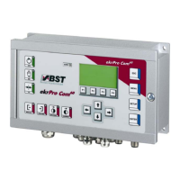
2. Alignment of the contrast sensor:
When scanning an interrupted line
, correct alignment
of the contrast sensor must be observed:
• The contrast sensor must be aligned so that the
edge
of the line is located in the sensor light spot.
• Only one
edge may be located within the light
spot.
correct
wrong wrong
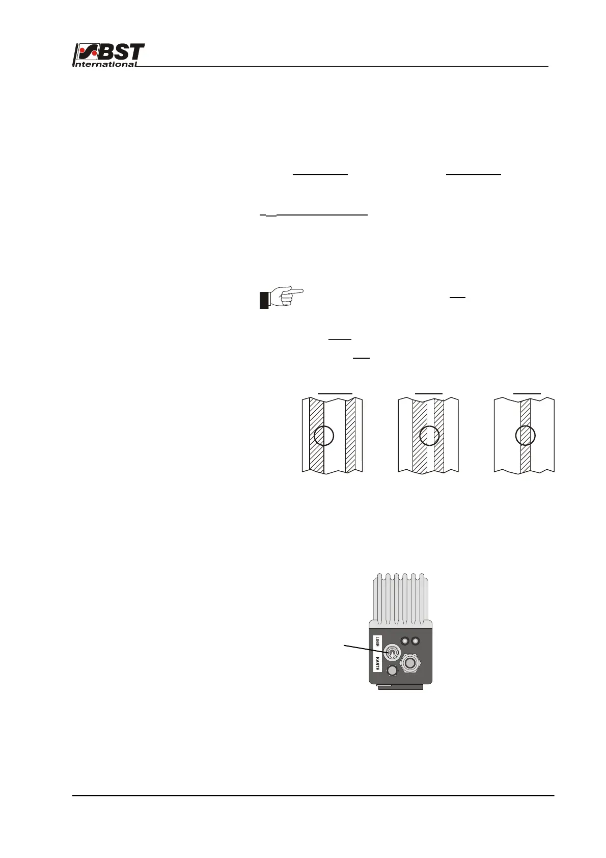
3. Operating mode setting for the contrast sensor T 62 D 1
The operating mode selection switch on the sensor must be set
to the position Kante (edge).
Operating mode
selection switch
300 m/min
60 s/min
8 mm
1000 mm/m