Installation B 1
ekrPro Com
60
web guide controller EDV No.: MD.191.01.05/1.6.x Chapter: B 1
with analog sensors Date: 23.11.2007 Page: 1/7
B 1 Installation
B 1.1 Installation site requirements
The ekrPro Com
60
controller must be installed in a dry, vibration-
free area.
Ambient conditions: Temperature: 0 to a max. 45°C
Humidity: 5 - 90%, no condensation
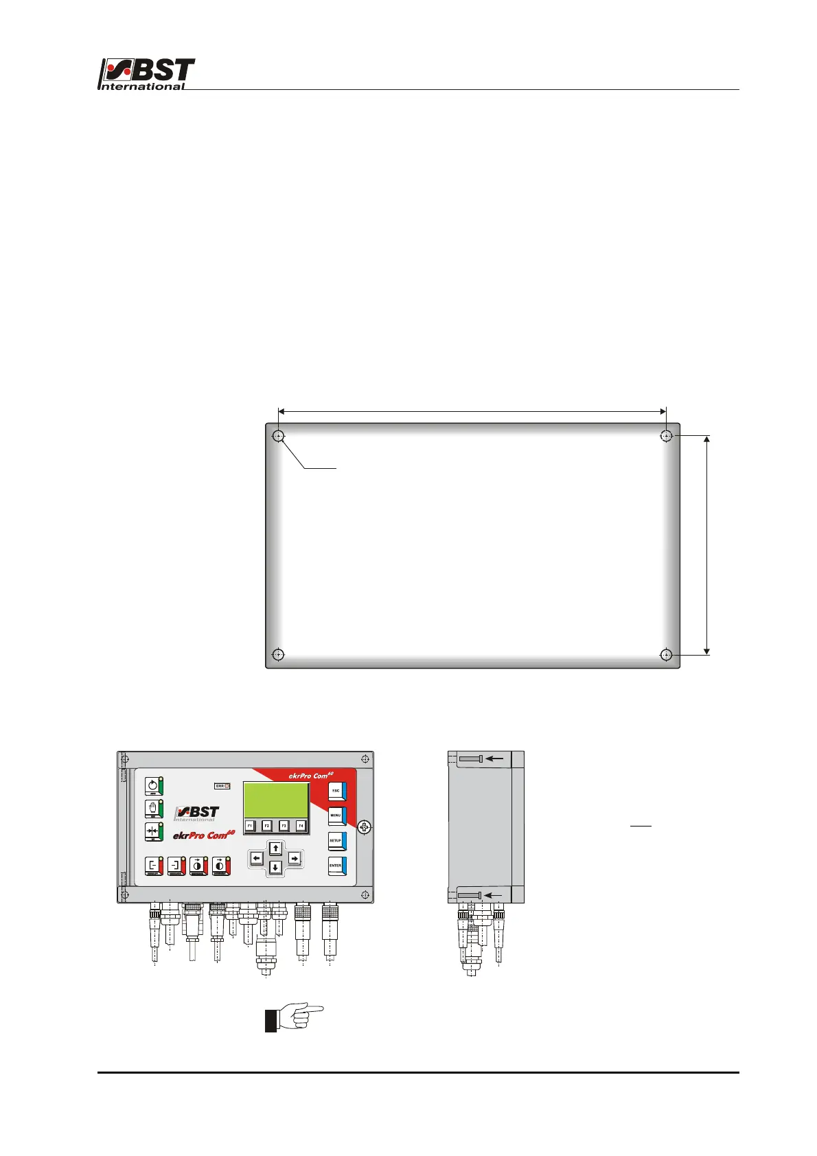
B 1.2 Installation ekrPro Com
60
(mounting unit)
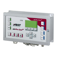
B 1.2.1 Securing hole diagram
B 1.2.2 Installation
1. Drill the securing holes as
shown in the mounting plan.
2. Use the four
securing
screws to attach the
housing.
3. Wire in the electric cables (if
required) or plug in the
necessary cable
connections.
Attention! A free area of at least 300 mm in front of the housing
must be guaranteed so that it can be opened.
ekrPro Com
60
housing
1
2
5
5
Ø
6