13
BÜCHI Mini Spray Dryer B-191 5 Operation
5 Operation
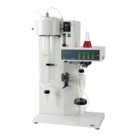
Figure 14: Operating and display elements on
the pneumatic nozzle cleaner
Make sure that the apparatus has been put into operation in
accordance with Chapter 4, Putting into operation.
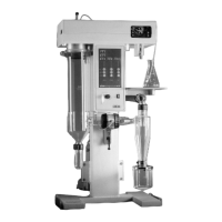
5.1 Layout of the operating and display elements
햲 Main switch
햳 Rotary switch for selection of air flow
햴 Inspection glass for air quantity
햵 Main switch, pump
햶 Main switch, aspirator
햷 Main switch, heating
햸 Main switch, pneumatic nozzle cleaner
햹 Main switch, magnetic stirrer
햺 Regulating push-button, pump
햻 Regulating push-button, aspirator
햽 Regulating push-button, heating
햾 Air flow regulation, “Sprayflow”
햿 Pressure selection adjustment, nozzle cleaner
헀 Nozzle cleaner interval adjustment
헁 LED display pump output in %
헂 LED display aspirator output in %
헃 LED display index values, input air temperature
헄 LED display actual value, input air temperature
헅 LED display actual value, output air temperature
헆 Flow meter for air flow rate in the nozzle (spray flow)
쎻 Manometer, nozzle cleaning pressure
쎻 Manometer filter, aspirator output (only for aspirator filter)
21
22
헁
헄
헂
햿
헀
헃
햵
햶
햷
햲
햳
햴
햻
햹
햺
햾
햸
Figure 13: Operating and display elements