Modules for Logamatic 4000 control panels - We reserve the right to make technical modifications.
11
Module installation for Logamatic 43xx controls 3
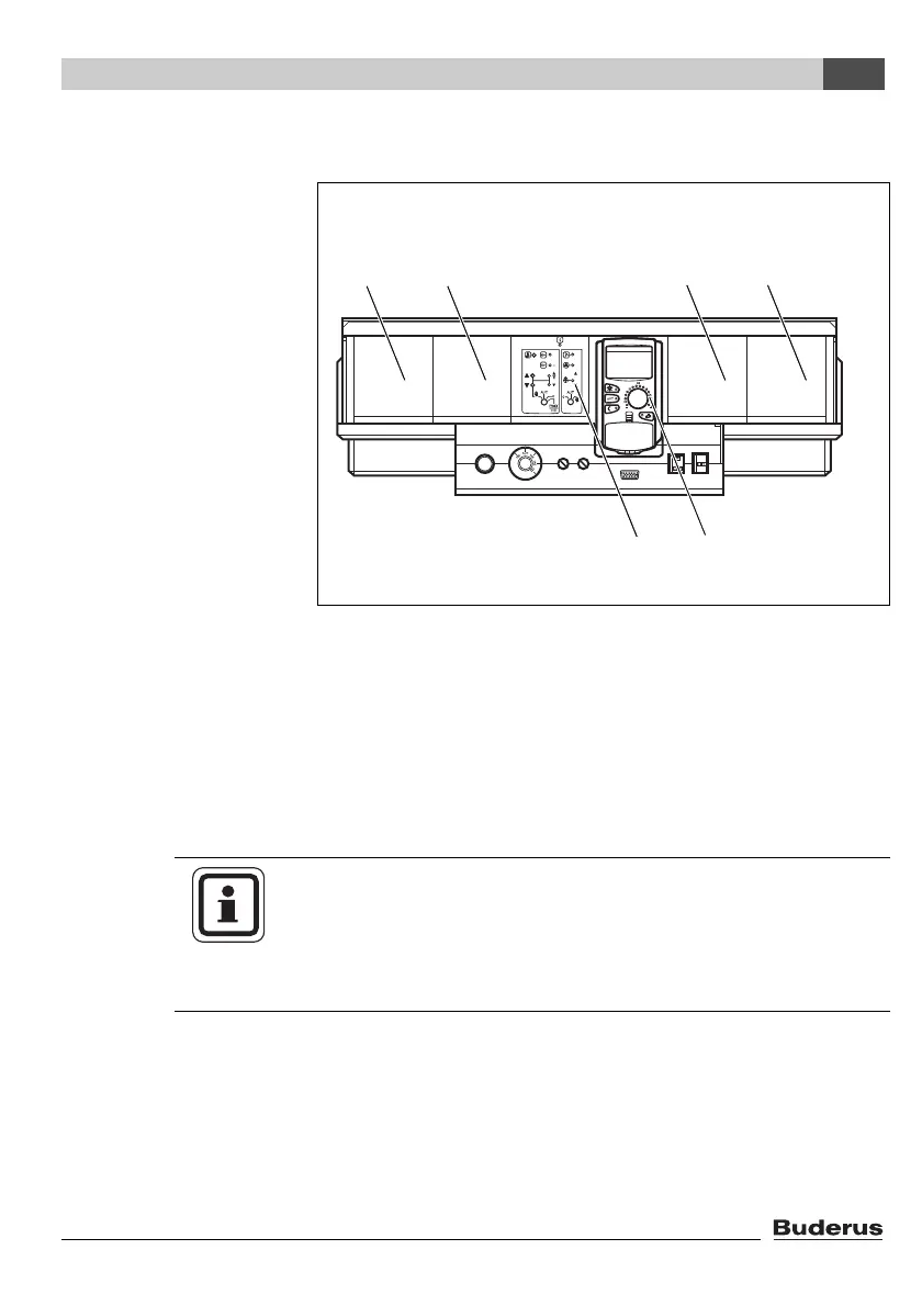
3.2 Arrangement of modules in the control panel
Generally you can install the additional modules in any free slot
(1 – 4). Make sure that the power supply leads from module to
module. For a sensible logical numbering of the heating zones,
insert the modules in order from left to right (slots 1 – 4).
Fig. 1 Layout of slots
1 Slot 1 for additional module
2 Slot 2 for additional module
3 Slot 3 for additional module
4 Slot 4 for additional module
5 Slot B behind MEC2 remote control
6 Slot A for central module ZM432 or ZM434 (standard equipment)
USER NOTE
Slot A (Æ Fig. 1, [6]) is always occupied by one of the central
modules ZM432 or ZM434; slot B (Æ Fig. 1, [5]) is always
occupied by the controller module CM431 and the MEC2 remote
control.