Do you have a question about the Buderus Logalux and is the answer not in the manual?
Defines warning symbols and keywords used in the document.
Provides essential safety guidelines for installation, servicing, and operation.
Guides users on safe operation, temperature settings, and maintenance.
Advice on annual inspection, maintenance, and spare parts.
Instructions regarding appliance safety after exposure to flood water.
Lists the components included in the DHW tank package.
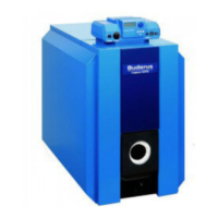
Specifies the intended application and limitations of the DHW tank.
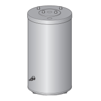
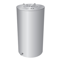
Details the components and features of the DHW tank with diagrams.
Locates and describes the information found on the tank's data plate.
Illustrates the pressure drop characteristics of the heating coil.
Presents detailed specifications and performance data for the DHW tank models.
Provides dimensions, clearances, and weight information for installation.
Covers initial steps for installing the DHW tank.
Specifies conditions for a suitable installation site.
Details required clearances around the tank for installation.
Guides on how to position and secure the tank during installation.
Outlines procedures for connecting the DHW tank to the water system.
Details the specific steps for water-side connections.
Instructions for installing the B-kit components.
Steps for installing the temperature and pressure relief valve.
Guide for installing temperature sensors or aquastats.
Specifics for using a Logamatic controller with the tank.
Instructions for installing the temperature sensor.
Steps for installing the aquastat accessory.
Instructions for reattaching insulation and the front panel.
Steps for initial startup and leak testing of the DHW tank.
Detailed steps for safely powering down and draining the DHW tank.
Procedure for frost protection shutdown.
Steps to safely prepare the tank before cleaning operations.
Methods for removing scale deposits from the tank interior.
Instructions for inspecting the sacrificial anode for wear.
Procedure for measuring the anode's protection current.
Steps for visually inspecting the magnesium anode.
Guide on how to replace a worn-out magnesium anode.
Procedures for safely restarting the tank after maintenance.
Detailed table of spare parts with order numbers and comments.
Illustrates spare parts for the DHW tank.
Table of spare parts, including specific model compatibility.
Exploded view of spare parts assembly.
Table of spare parts with order numbers and comments.
| Insulation | Polyurethane foam |
|---|---|
| Material | Steel |
| Capacity | Varies by model (e.g., 200L, 300L) |
| Thermal Insulation | polyurethane foam |
| Maximum Operating Pressure | 10 bar |
| Maximum Temperature | 95°C |
| Connection Size | Varies by model |
| Anode | Magnesium anode |
| Certification | CE |