7 Systems
6 720 646 864 (12/2010) – Technical guide Logano GE315, GE515 and GE615
48
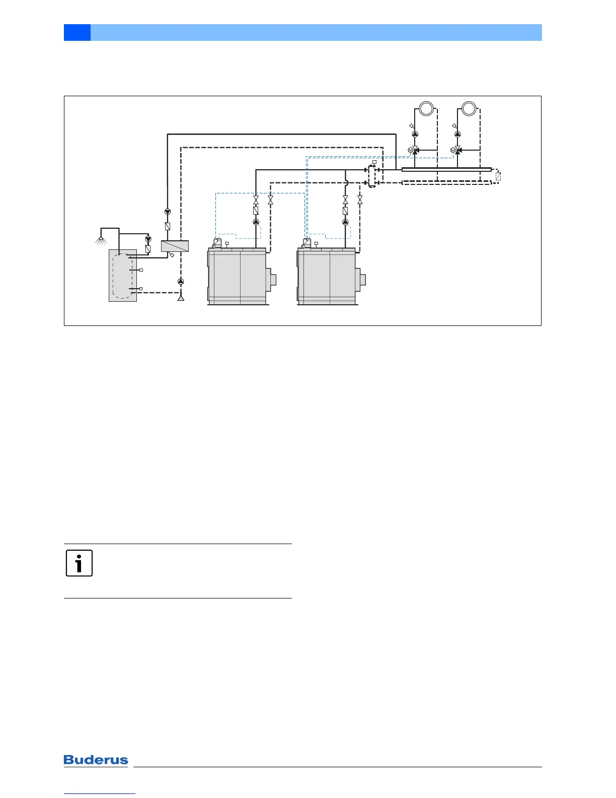
7.7 2-boiler system with boiler control and heating circuit control, plus hydraulic
balancing
Fig. 37 System example for two Ecostream cast iron boilers; DHW heating with primary store system; number and
version of the heating circuits dependent on the Logamatic control unit
EK Cold water inlet
FK Boiler water temperature sensor
FV Flow temperature sensor
FVS Strategy flow temperature sensor
FW DHW temperature sensor
HK Heating circuit
KR Check valve
PH Heating circuit pump
PK Feed pump
PS Primary circuit pump
PW Stratification pump
PZ DHW circulation pump
RK Return
SH Heating circuit actuator
VK Boiler flow
WT Heat exchanger
1 Primary store system (DHW cylinder as option)
Application area
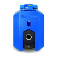
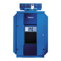
• Ecostream cast iron boilers Logano GE315, GE515
and GE615
• Boiler control and heating circuit control (heating
circuits with actuators) with Logamatic 4211 or 4311
control unit
Function description
The boiler sequence can be controlled via the multi boiler
strategy module subject to load and time. If the
temperature at the strategy sensor FVS falls below the set
flow temperature, the Logano (1) lead boiler starts. The
lag boiler is hydraulically shut off via the check valve KR in
the boiler flow. If the heat demand increases, the Logano
(2) lag boiler is automatically switched on. If the load falls,
the switching processes run in reverse order.
The Logamatic control unit safeguards the operating flow
temperature of both boilers. If the operating flow
temperature at temperature sensor FK1 or FK2 falls
below the set value when the burner is on, the control unit
reduces the flow rate in the flow by overriding control of
the heating circuit actuators SH until the operating
temperature has been reached.
Special engineering information
• In conjunction with hydraulic balancing, the feed
pumps PK are advisable if there are several distributor
stations, or if these are far apart. A low loss header or
low-pressure distributor with bypass and check valve
can be used for hydraulic balancing.
• A low loss header is also suitable for de-sludging.
• Distribute the total output between the boilers so each
has 50 %. If the output is distributed differently,
safeguard the flow rates using suitable measures
(sizing the pipework and/or pumps).
HK2HK1
SH2
PH2
SH1
PH1
VK
RK
FV1
FV2
FK2
VK
RK
FK1
FVS
KR
KR
PS
PW
FW2
KR
PZ
FW3
FW1
EK
WT
KR
PK2
KR
PK1
6 720 644 097-31.1il
Logano (2) Logano (1) 1
The circuit diagram is only a schematic
illustration!
For information on all system examples,
Æ page 36.
 Loading...