2
Product information
Logano plus GB312 – 6 720 806 273 (2013/01)8
2.8 Product information
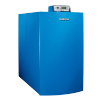
The Logano plus GB312 ( Fig. 1) is supplied with a fully factory-
installed and wired Logamatic BC10 basic control unit
( Fig. 2, page 9).
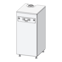
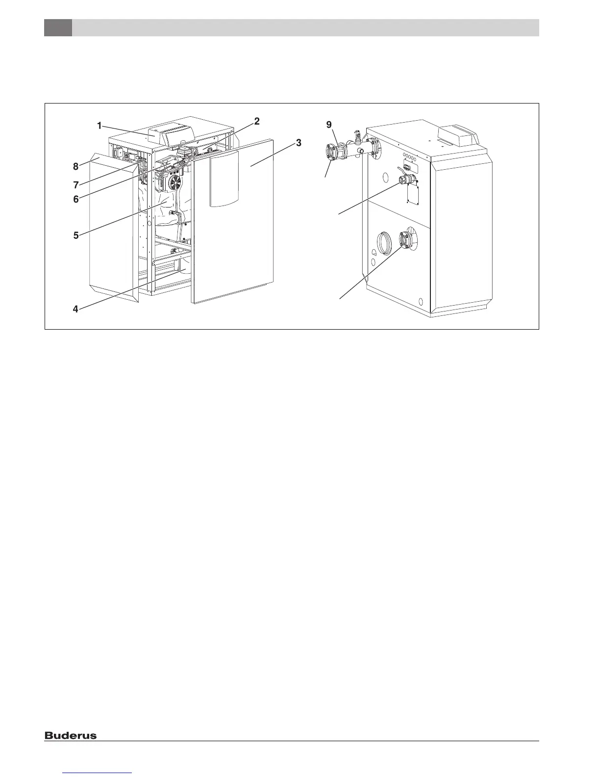
Fig. 1 Logano plus GB312 - main components
[1] Programmer (MC10 and BC10)
[2] Gas burner
[3] Boiler front panel
[4] Siphon (condensate trap)
[5] Boiler block with insulation
[6] Ignition Control
[7] Gas valve
[8] Boiler side panel
[9] B-kit with supply check valve (supplied as standard, not factory
installed)
[10] Gas gas shutoff valve (supplied as standard, not factory-installed)
[11] Mating flange, 2½ " (included in B-kit, not factory-installed)
[12] Bolts, washers, lock washers and nuts (to mount supply manifold
and mating flanges)
The main components of the Logano plus GB312 ( Fig. 1) are:
• Controller
• Frame and jacket
• Boiler block with insulation
• Gas burner
• B-kit (standard B-kit comprising temperature/pressure gauge,
pressure relief valve, supply manifold, supply check valve, mating
flange for supply/return piping, not factory installed)
• Gas shutoff valve
The controller monitors and controls all electrical boiler components.
The boiler block transfers the heat generated by the burner to the
heating water. The thermal insulation reduces the radiation and standby
losses.
7 747 010 720-01.3RS
10
11
12
 Loading...