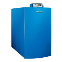
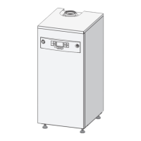
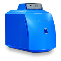
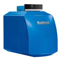
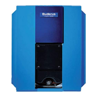
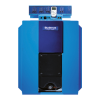
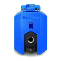
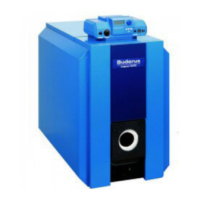
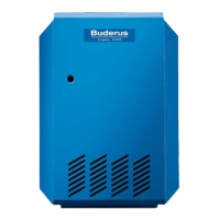
GB312 Applications Manual
_
Table of Contents
1 Product description 4
1.1 Package contents 6
1.2 Dimensions and specifications 7
2 Installing the boiler 10
2.1 Recommended wall clearances 10
2.2 Leveling the boiler 11
3 Water quality requirements 12
3.1 Maintenance of user manual 12
3.2 Prevention of damage by corrosion 12
3.3 Water hardness 13
3.4 Checking max quantity of first fill water based
on water quality 13
3.5 pH requirements 13
3.6 Operator’s log 15
4 Openings for combustion air supply
& venting 16
5 Venting requirements 17
5.1 Connecting the air supply (for direct vent operations) 19
5.2 Installing the wall exit for air supply pipe 19
5.3 Installing the roof exit for air pipe 20
5.4 Design of flue and air pipe for balanced flue operation
(refer to NFPA54 ANSIZ223.1 for dimensions) 21
5.5 Venting system calculation/sizing chart 22
6 Piping the boiler 26
6.1 Connecting central heating supply 26
6.2 Fitting the heating system return 26
6.3 Installing the DHW Tank 26
6.4. Installing the condensate drain 26
6.5 Connecting the fuel supply 27
6.6 Pipe sizing 29
7 CSD-1 Kit 31
7.1 Operating Addendum for the GB312 in High
Temperature Applications 33
8 Internal boiler wiring diagram 34
9 MC10 wiring diagram 35
10 Sequence of operations 36
11 High altitude adjustment 37
11.1 General 37
11.2 Adjustments 37
11.3 CO
²
adjustment of the burner / adjustment
of the gas valve 37
11.4 Setting for speed of burner fan 40
12 Examples of installations 42
12.1 Legend 42
12.2 Single boiler systems 43
12.3 Multiple boiler systems 49
13 Pump and low loss header selection 57
13.1 Pump & low loss header (hydro-separator) selection 57
13.2 Low loss header selection per manufacturer 58
 Loading...


